1. Introduction
The Seco-Larm SA-025Q is a versatile timer module designed for a wide range of timed security and access control operations. It supports applications such as door unlock timing, siren or bell activation, and more. Its 12-24VDC auto-sensing operation and DIP switch programming simplify installation and configuration.
2. Features
- Timer duration adjustable from 1 second to 60 minutes.
- Trigger options include positive voltage (+DC), closure of a dry contact, or opening of a dry contact.
- Relay programmable to activate at the start or end of the timing cycle.
- Relay programmable for a one-second activation at the end of the timing cycle.
- Relay programmable for pulse (flash) activation.
- Built-in reset function for manual timing cycle reset.
- Form-C relay contacts rated 8A@120VAC/24VDC.
- LED indicator for relay energized status.
- 12VDC/24VDC operation (auto-sensing).
- Current consumption: 1mA (standby), 50mA (active).
- Board dimensions: 2 1/8" x 2 1/2" (73x63 mm).
3. Installation and Setup
The SA-025Q timer module is designed for easy integration into various systems. Ensure power is disconnected before installation.
3.1 Product Overview
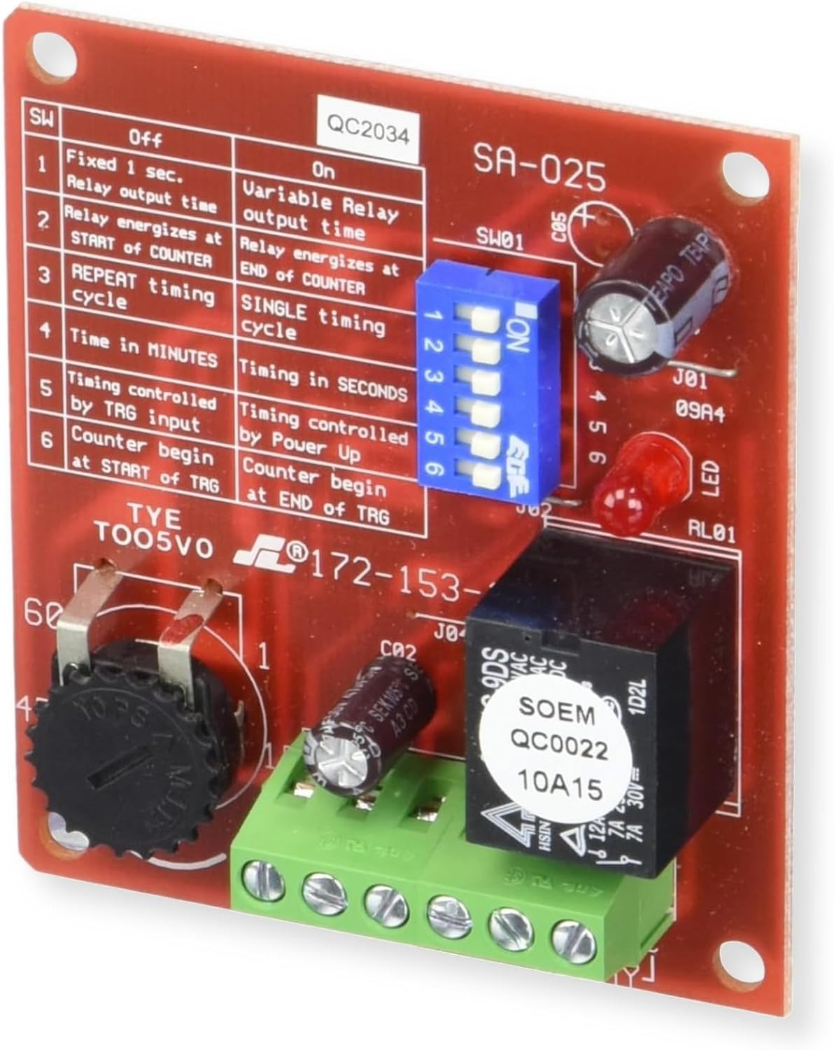
Figure 1: Seco-Larm SA-025Q Multi-Purpose Programmable Timer circuit board. This image displays the main components including the DIP switches, relay, and terminal block for connections.
3.2 DIP Switch Settings
The SA-025Q's functions are programmed via six DIP switches. Refer to the table below for switch configurations.
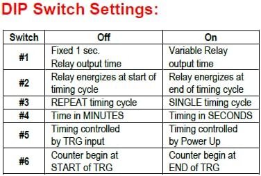
Figure 2: DIP Switch Settings. This table details the function of each of the six DIP switches, indicating their 'Off' and 'On' states.
| Switch | OFF Position | ON Position |
|---|---|---|
| #1 | Fixed 1 sec. Relay output time | Variable Relay output time |
| #2 | Relay energizes at START of timing cycle | Relay energizes at END of timing cycle |
| #3 | REPEAT timing cycle | SINGLE timing cycle |
| #4 | Time in MINUTES | Timing in SECONDS |
| #5 | Timing controlled by TRG input | Timing controlled by Power Up |
| #6 | Counter begin at START of TRG | Counter begin at END of TRG |
3.3 Wiring Diagram (Sample Application)
The following diagram illustrates a typical application where the SA-025Q is connected to an electric strike (SD-995C) and an N.O. contact or switch. The output is set via the DIP switches for a momentary trigger with no delay.

Figure 3: Sample Application Wiring Diagram. This diagram shows how to connect the SA-025Q to a power supply, an N.O. contact/switch, and an electric strike for a timed release function.
For specific wiring, connect the 12-24VDC power supply to the designated terminals. The trigger input (TRG) can be connected to a dry contact or switch. The Form-C relay output (NO, COM, NC) should be wired to the device being controlled, such as an electric strike or siren.
4. Operation
Once installed and configured with the DIP switches, the SA-025Q operates based on the selected timing mode and trigger input. When the trigger condition is met (e.g., dry contact closure), the timer initiates. The relay will activate according to the programmed duration and activation point (start or end of cycle).
- Timing Adjustment: Use the potentiometer on the board to fine-tune the variable relay output time when DIP Switch #1 is in the 'ON' position.
- Triggering: The timer can be triggered by a positive voltage, closing a dry contact, or opening a dry contact, depending on the wiring and application.
- Reset Function: The built-in reset function allows for manual interruption and restart of the timing cycle.
5. Specifications
| Specification | Value |
|---|---|
| Model Number | SA-025Q |
| Brand | Seco-Larm |
| Operating Voltage | 12-24VDC (Auto-sensing) |
| Current Consumption | 1mA (Standby), 50mA (Active) |
| Timer Range | 1 second to 60 minutes |
| Relay Type | Form-C |
| Relay Contact Rating | 8A@120VAC/24VDC |
| Programming | DIP Switches |
| Board Dimensions | 2 1/8" x 2 1/2" (73x63 mm) |
| Material | Metal (for components) |
| Item Weight | 0.15 Pounds |
6. Troubleshooting
No specific troubleshooting information is provided in the available product data. For issues, verify all wiring connections, ensure correct power supply voltage, and confirm DIP switch settings match the desired operation. Consult a qualified technician if problems persist.
7. Maintenance
No specific maintenance information is provided in the available product data. The SA-025Q is designed for low maintenance. Keep the unit free from dust and moisture. Do not attempt to repair the circuit board yourself.
8. Warranty and Support
No specific warranty or support contact information is provided in the available product data. Please refer to the manufacturer's official website or your point of purchase for warranty details and technical support.