
Miller 250101
Miller 250101 Control Switch Assembly User Manual
Model: 250101 | Brand: Miller
1. Introduction
This user manual provides essential information for the safe and effective use, installation, and maintenance of the Miller 250101 Control Switch Assembly. Please read this manual thoroughly before attempting to install or operate the device. Retain this manual for future reference.
The Miller 250101 is a critical component designed for specific control applications within welding and industrial equipment, ensuring precise operation and reliability.
2. Safety Information
WARNING: ELECTRIC SHOCK HAZARD
- Always disconnect power to the equipment before installing, servicing, or removing the control switch assembly.
- Installation and service should only be performed by qualified personnel.
- Ensure all connections are secure and properly insulated to prevent short circuits or electrical hazards.
- Do not operate the switch if it appears damaged or has been exposed to moisture.
Proposition 65 Warning:
This product may contain chemicals known to the State of California to cause cancer, birth defects, or other reproductive harm. For more information, visit www.P65Warnings.ca.gov.
3. Product Overview
The Miller 250101 Control Switch Assembly is a compact and durable component designed for integration into various Miller welding and industrial systems. It features a robust housing and pre-wired leads for straightforward connection.

Figure 3.1: Front view of the Miller 250101 Control Switch Assembly, showing the black switch body, lever, and yellow-sleeved white wires with terminal ends.
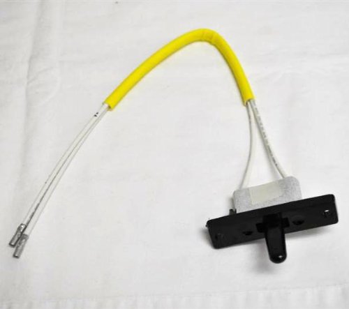
Figure 3.2: Top-down view of the Miller 250101 Control Switch Assembly, highlighting the yellow insulated wires and the black switch mechanism, resting on a white fabric surface.
4. Setup and Installation
The Miller 250101 Control Switch Assembly is designed for integration into existing Miller equipment. Specific installation procedures will vary depending on the host machine. Always refer to the primary equipment's service manual for detailed wiring diagrams and installation instructions.
- Power Disconnection: Ensure the main power to the equipment is completely disconnected and locked out before beginning any installation.
- Locate Mounting Position: Identify the designated mounting location for the control switch assembly within your equipment.
- Secure the Switch: Mount the switch assembly using appropriate fasteners (not included) to ensure it is firmly secured and does not vibrate loose during operation.
- Wire Connections: Connect the pre-wired leads of the 250101 assembly to the corresponding terminals on the equipment's control board or wiring harness. Pay close attention to polarity and wire color coding as specified in your equipment's manual.
- Verify Connections: Double-check all wiring connections for correctness and tightness. Ensure no bare wires are exposed.
- Reassemble: Carefully reassemble any covers or panels removed during installation.
- Test: Restore power and perform a functional test of the switch assembly according to the equipment's operational guidelines.
5. Operating Instructions
The Miller 250101 Control Switch Assembly functions as an integral part of your Miller equipment's control system. Its operation is typically straightforward, involving a simple toggle or push action to activate or deactivate a specific function.
- Functionality: The exact function controlled by this switch (e.g., power on/off, mode selection, specific process activation) is determined by the equipment it is installed in. Refer to your primary equipment's user manual for details on the switch's specific role.
- Activation: Operate the switch lever or button as required by your equipment's design. Ensure a firm and deliberate action.
- Indicator: If your equipment includes an indicator light associated with this switch, observe it to confirm the desired function has been activated or deactivated.
Note: Avoid excessive force when operating the switch. If the switch feels stiff or unresponsive, do not force it. Consult the troubleshooting section or a qualified technician.
6. Maintenance
The Miller 250101 Control Switch Assembly is designed for minimal maintenance. Regular inspection and cleaning will help ensure its longevity and reliable performance.
- Cleaning: Periodically clean the exterior of the switch with a soft, dry cloth. Do not use abrasive cleaners, solvents, or excessive moisture.
- Inspection: Regularly inspect the switch for any signs of physical damage, such as cracks, loose connections, or frayed wires.
- Environmental Protection: Ensure the switch is not exposed to excessive dust, moisture, or corrosive environments beyond its IP54 rating.
- Connection Integrity: Check that the electrical connections remain tight and free from corrosion.
CAUTION:
Do not attempt to disassemble the control switch assembly. There are no user-serviceable parts inside. Disassembly will void any warranty and may lead to damage or injury.
7. Troubleshooting
If you experience issues with the Miller 250101 Control Switch Assembly, consider the following common troubleshooting steps. Always ensure power is disconnected before inspecting wiring.
| Problem | Possible Cause | Solution |
|---|---|---|
| Switch is unresponsive | Loose or disconnected wiring; Internal fault; Incorrect installation. | Check all wiring connections. Ensure proper installation as per equipment manual. If problem persists, replace the switch. |
| Intermittent operation | Poor connection; Contamination; Worn contacts. | Inspect connections for corrosion or looseness. Clean switch exterior. If issue continues, replacement may be necessary. |
| Physical damage to switch | Impact; Improper handling. | Replace the damaged switch immediately to prevent further issues or safety hazards. |
If troubleshooting steps do not resolve the issue, contact Miller customer support or a qualified service technician.
8. Specifications
| Attribute | Detail |
|---|---|
| Brand | Miller |
| Model Number | 250101 |
| Product Dimensions | 6 x 1 x 1 inches; 3.2 ounces |
| Item Dimensions (L x W x H) | 6 x 1 x 1 inches |
| Manufacturer | Miller Electric |
| ASIN | B004SELDDC |
| International Protection Rating | IP54 (Dust protected and splash resistant) |
| Connectivity Protocol | Wi-Fi (Note: This specification is listed in product data. Its relevance to a simple control switch assembly should be verified with Miller Electric if direct Wi-Fi control is not expected.) |
| Unit Count | 1.0 Count |
| Number of Items | 1 |
| UPC | 715959566773 |
9. Warranty and Support
For specific warranty information regarding the Miller 250101 Control Switch Assembly, please refer to the warranty documentation provided with your original Miller equipment or contact Miller Electric directly. Warranty terms typically cover defects in materials and workmanship under normal use.
Customer Support:
If you require technical assistance, replacement parts, or have questions not covered in this manual, please contact Miller Electric customer support. Visit the official Miller website for the most current contact information and support resources.
Note: Unauthorized repairs or modifications to the control switch assembly may void the warranty.
Ask a question about this manual
Ask about setup, troubleshooting, compatibility, parts, safety, or missing instructions. Manuals+ will review the question and use this page’s manual context to help answer it.