1. Introduction and Overview
This manual provides essential information for the safe and effective installation, operation, and maintenance of your HELLA 6EK 002 843-001 Battery Main Switch. This device is designed to provide effective safety against theft and fire hazards by disconnecting the vehicle's electrical circuit. Please read this manual thoroughly before attempting any installation or operation.
2. Safety Information
Always adhere to the following safety guidelines to prevent injury or damage to the product and vehicle:
- Always disconnect the vehicle's main power source (e.g., battery terminals) before beginning any installation or maintenance work on the switch.
- Ensure proper insulation and secure connections to prevent short circuits, which can lead to fire or electrical shock.
- Wear appropriate personal protective equipment (PPE), such as safety glasses and insulated gloves, when working with electrical systems.
- Do not exceed the specified current and voltage ratings of the switch.
- Consult a qualified technician if you are unsure about any installation steps or electrical procedures.
- Keep the switch and its connections dry and free from contaminants.
3. Product Features
The HELLA 6EK 002 843-001 Battery Main Switch offers the following key features:
- Battery switch with a distinctive red turn knob key for clear identification and control.
- Designed to switch off either the positive (+) or negative (-) battery line, providing flexibility in installation.
- The key can be removed in the "Off" position, offering an additional layer of security against unauthorized use.
- Features two robust screw connections, each supplied with two screw nuts for secure cable attachment.
- Supports various supply line cross-sections for continuous current: 35 mm² at 100A, 70 mm² at 250A, and 250 mm² at 500A.
- High capacity at 12V: maximum 1000A for 10 seconds.
- Rated with DIN/ISO 40050-IPX2 for protection against dripping water.
- Replacement key part number: 9SL 706 729-031.
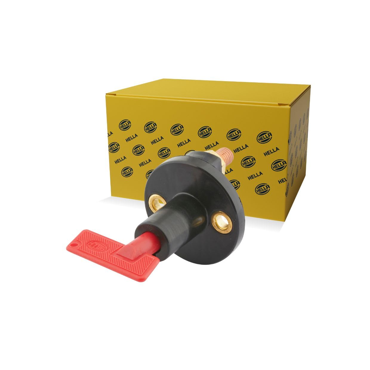
Image showing the HELLA 6EK 002 843-001 Battery Main Switch, featuring its red turn knob control and two bolted screw connections.
4. Setup and Installation
Follow these steps for proper installation of the battery main switch:
- Choose Mounting Location: Select a secure, dry, and easily accessible location for the switch. Ensure the mounting surface is clean and stable.
- Prepare Wiring: Determine whether you will disconnect the positive (+) or negative (-) battery line. Cut the appropriate battery cable to size, ensuring enough slack for connection. Strip the ends of the cable to expose the conductor.
- Mount the Switch: Securely bolt the switch to the chosen mounting surface. Ensure it is firmly attached to prevent movement or vibration damage.
- Connect Battery Cables: Connect the prepared battery cables to the two screw connections on the switch. Ensure the correct cable cross-section is used as specified in the product features (e.g., 35 mm² for 100A, 70 mm² for 250A). Place the screw nuts over the bolts and tighten them securely to ensure a low-resistance connection.
- Verify Connections: Double-check all connections for tightness and proper insulation. Ensure no bare wires are exposed that could cause a short circuit.
- Test Operation: Insert the red switch key into the switch. Turn the key to the 'ON' position to establish the circuit. Verify that power is restored to the vehicle's systems. Turn the key to the 'OFF' position and remove it to ensure the circuit is properly disconnected.
5. Operating Instructions
Operating the HELLA Battery Main Switch is straightforward:
- To Activate the Circuit (Power ON): Insert the red switch key into the switch. Turn the key clockwise to the 'ON' position. The switch will forcibly close the vehicle's circuit, allowing power to flow.
- To Deactivate the Circuit (Power OFF): Turn the red switch key counter-clockwise to the 'OFF' position. The circuit will open (separate) by a return spring, disconnecting power. The key can then be removed for security, preventing unauthorized activation.
6. Maintenance
Regular maintenance ensures the longevity and reliable operation of your battery main switch:
- Periodic Inspection: Regularly inspect the switch and its connections for any signs of wear, corrosion, or damage. Check for loose wires or cracked housing.
- Connection Tightness: Ensure all screw connections and mounting bolts remain tight. Loose connections can lead to resistance, heat buildup, and potential failure.
- Cleaning: Keep the switch clean and free from dirt, dust, and moisture. Use a dry, soft cloth for cleaning. Do not use harsh chemicals or abrasive materials.
- Replacement: If any damage is observed, if the switch fails to operate correctly, or if the key becomes difficult to turn, replace the switch immediately. A replacement key (part number 9SL 706 729-031) can be obtained if only the key is lost or damaged.
7. Troubleshooting
If you encounter issues with your HELLA Battery Main Switch, refer to the following troubleshooting guide:
| Problem | Possible Cause | Solution |
|---|---|---|
| No power when switch is in 'ON' position. | Loose battery connections. Key not fully turned to 'ON'. Damaged wiring or switch. | Check and tighten all battery and switch connections. Ensure the key is fully engaged and turned to the 'ON' position. Inspect wiring for damage; replace switch if faulty. |
| Switch feels loose or wobbly. | Loose mounting bolts. | Tighten the mounting bolts securing the switch to its surface. |
| Key is difficult to turn or remove. | Dirt or debris in the mechanism. Internal damage. | Ensure the switch mechanism is clean. Do not force the key. If the issue persists, the switch may be damaged and require replacement. |
| Visible corrosion on terminals. | Exposure to moisture or harsh environment. | Clean terminals with a wire brush and battery terminal cleaner. Apply anti-corrosion grease. Ensure connections are sealed from moisture. |
8. Specifications
| Specification | Value |
|---|---|
| Model Number | 6EK 002 843-001 |
| Operation Mode | ON-OFF |
| Current Rating (Continuous) | 250 Amps |
| Capacity at 12V | Max 1000A / 10 seconds |
| Operating Voltage | 12 Volts |
| Contact Type | Normally Open |
| Connector Type | Screw (2 connections) |
| Material (Housing) | Plastic |
| Material (Contact) | Metal |
| Product Dimensions (L x W x H) | 9.2 x 7.5 x 7.5 cm |
| Item Weight | 0.13 Kilograms |
| International Protection Rating | IPX2 (DIN/ISO 40050) |
| Thread Pitch | 1.5mm |
| Compatible Vehicle Types | Ambulance, Truck, Forklift, Police Car, Boat |
9. Warranty and Support
For warranty information, technical assistance, or to inquire about replacement parts, please contact your authorized HELLA dealer or visit the official HELLA website. Please retain your purchase receipt as proof of purchase for any warranty claims.