1. Introduction
This manual provides detailed instructions for the installation, operation, and maintenance of the Ortronics 48-Port Cat5e Patch Panel, Model OR-851004038. This patch panel is designed for efficient organization and termination of Cat5e Ethernet cables in a structured cabling system, supporting T568B wiring standards. Proper installation ensures optimal network performance and longevity of the product.
2. Safety Information
- Always disconnect power to any active network equipment before performing installation or maintenance on the patch panel.
- Ensure proper grounding of the rack and patch panel to prevent electrical hazards and ensure signal integrity.
- Use appropriate tools for cable termination (e.g., 110 punchdown tool) to avoid injury and ensure correct connections.
- Do not expose the patch panel to excessive moisture or extreme temperatures.
- Handle the patch panel with care to prevent damage to connectors or internal components.
3. Package Contents
Verify that all items listed below are present in the package. If any items are missing or damaged, contact your supplier immediately.
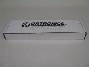
Figure 3.1: Ortronics 48-Port Cat5e Patch Panel with included accessories and packaging.
- Ortronics 48-Port Cat5e Patch Panel (Model OR-851004038)
- Mounting screws/hardware
- Cable ties or management clips
- Installation instructions/documentation
4. Setup and Installation
4.1 Mounting the Patch Panel
The Ortronics 48-Port Cat5e Patch Panel is designed for standard 19-inch rack mounting. Ensure the rack is stable and properly grounded before installation.
- Align the mounting holes on the patch panel with the corresponding holes on the rack rails.
- Secure the patch panel to the rack using the provided mounting screws. Ensure it is firmly attached and level.
4.2 Wiring the Patch Panel (T568B Standard)
This patch panel supports the T568B wiring standard. Refer to the color codes on the rear of the panel for correct termination. A 110 punchdown tool is required.
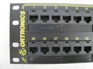
Figure 4.1: Front view of the patch panel, displaying RJ45 ports and numbering.

Figure 4.2: Another front view of the patch panel, showing the higher numbered ports.
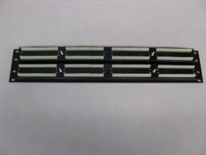
Figure 4.3: Rear view of the patch panel, illustrating the 110 punchdown termination blocks.

Figure 4.4: Detailed rear view of punchdown blocks, specifically for ports 25-30, showing color coding.

Figure 4.5: Detailed rear view of punchdown blocks, specifically for ports 1-6, showing color coding.
- Strip approximately 1-2 inches of the outer jacket from the Cat5e cable. Be careful not to nick the inner wire insulation.
- Untwist the wire pairs as little as possible, maintaining the twists close to the jacket.
- Following the T568B color code diagram printed on the rear of the patch panel, place each wire into its corresponding slot on the 110 punchdown block.
- Use a 110 punchdown tool to firmly seat each wire into its slot. The tool should trim any excess wire automatically.
- Repeat for all 48 ports. Ensure all connections are secure and wires are properly seated.
- Use cable ties to manage and secure the terminated cables, reducing strain on the connections.
5. Operating Instructions
Once the patch panel is installed and wired, it functions as a central connection point for your network infrastructure.
- Connect your network devices (e.g., computers, IP phones, access points) to the front RJ45 ports of the patch panel using standard Cat5e patch cables.
- Connect the rear-terminated cables from the patch panel to your network switch or router.
- Verify network connectivity for each connected device. Use a cable tester to confirm proper termination if issues arise.
6. Maintenance
- Cleaning: Periodically clean the front RJ45 ports with a lint-free cloth and a specialized network connector cleaner. Avoid using abrasive materials or harsh chemicals.
- Inspection: Regularly inspect all cable connections for signs of wear, damage, or loose terminations. Re-terminate any compromised connections.
- Cable Management: Ensure proper cable management is maintained to prevent strain on ports and cables, which can lead to performance degradation or damage.
7. Troubleshooting
| Problem | Possible Cause | Solution |
|---|---|---|
| No network connectivity on a port. | Incorrect or loose cable termination; faulty patch cable; faulty network device. |
|
| Slow network speed. | Poor cable termination; cable exceeding maximum length; electromagnetic interference (EMI). |
|
| Intermittent connection. | Loose connection; damaged cable; faulty port. |
|
8. Specifications
| Feature | Detail |
|---|---|
| Brand | Ortronics |
| Model Number | OR-851004038 |
| Cable Type | Cat5e Ethernet |
| Number of Ports | 48 |
| Wiring Standard | T568B (110 punchdown) |
| Mounting | 19-inch Rack Mount |
| Indoor/Outdoor Usage | Indoor, Outdoor |
| ASIN | B00499YBQC |
Note: Specifications are subject to change without notice.
9. Warranty and Support
Ortronics products are manufactured to high-quality standards. For specific warranty information, please refer to the warranty card included with your product or visit the official Ortronics website.
For technical support, product inquiries, or to report issues, please contact Ortronics customer service through their official channels. Contact information can typically be found on the product packaging or the manufacturer's website.