1. Introduction
This instruction manual provides comprehensive information for the proper installation, operation, and maintenance of the Federal Signal 650 Series Siren, Model 650001. The 650 Series Siren is a microprocessor-based amplifier designed to provide advanced sound and light control functions through its compact microphone control head. Please read this manual thoroughly before attempting any installation or operation to ensure safe and effective use of the product.
2. Safety Information
WARNING: This product can expose you to chemicals including lead, which is known to the State of California to cause cancer and birth defects or other reproductive harm. For more information, go to www.P65Warnings.ca.gov.
Always ensure that all electrical connections are made by qualified personnel and adhere to local and national electrical codes. Disconnect power before servicing. Improper installation or use can result in product damage, property damage, or personal injury.
3. Product Overview
The Federal Signal 650 Series Siren system consists of a main amplifier unit, a microphone control head, and associated mounting hardware. It features a 100 Watt output and various siren tones.
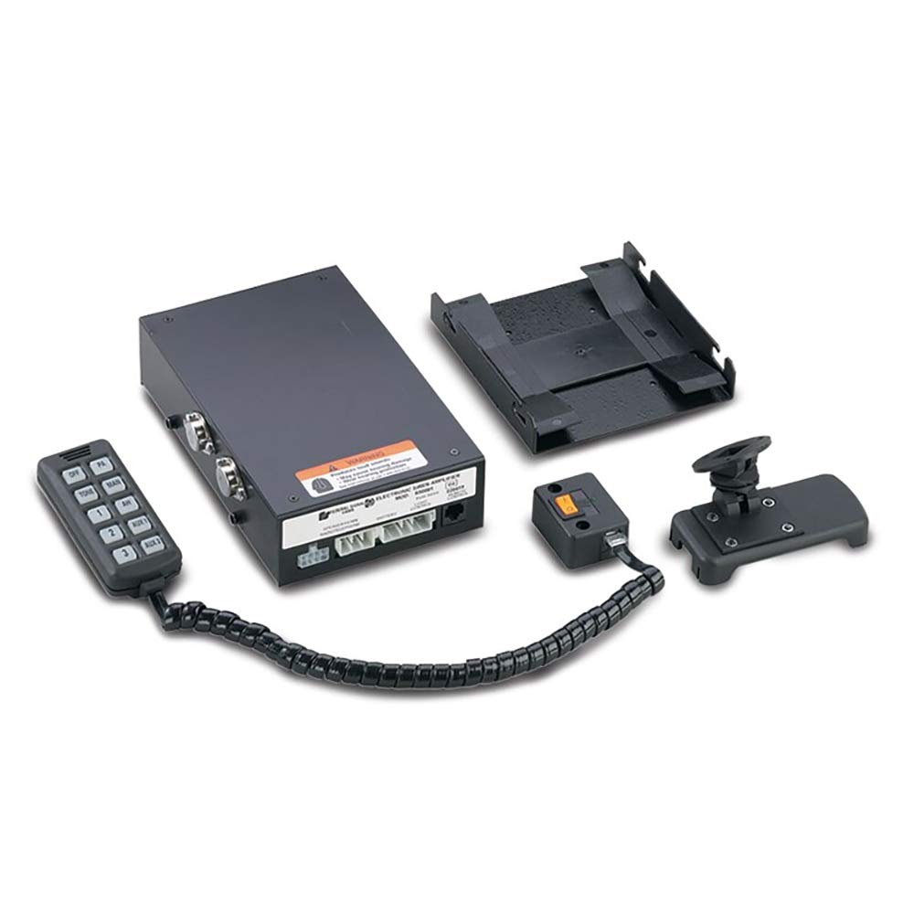
Figure 1: Federal Signal 650 Series Siren system showing the main amplifier unit, microphone control head, and mounting bracket.
Key Features:
- 3-position push button control on the microphone.
- Backlit and rubberized microphone control head for enhanced visibility and grip.
- Eight (8) 10-amp light and auxiliary relay positions for external device control.
- 100 Watt output with Wail, Priority, Air Horn, Manual Peak, and Hold tones.
- Horn ring transfer capability.
- Remote on/off switch box with built-in Public Address (PA) volume control.

Figure 2: Close-up view of the microphone control head, displaying the various push buttons for siren and auxiliary functions.
4. Setup and Installation
Installation of the Federal Signal 650 Series Siren should be performed by a qualified technician. Ensure the vehicle's battery is disconnected before beginning installation.
4.1 Mounting the Amplifier Unit
- Select a dry, secure location within the vehicle, away from excessive heat or moisture.
- Use the provided mounting bracket to securely fasten the amplifier unit. Ensure adequate ventilation around the unit.
4.2 Mounting the Microphone Control Head
- Mount the microphone control head in an easily accessible location for the operator, ensuring it does not obstruct airbags or driver visibility.
- Route the coiled cord safely, preventing interference with vehicle controls.
4.3 Electrical Connections
- Power: Connect the main power wires to the vehicle's battery, ensuring proper fusing and polarity.
- Speaker: Connect the siren speaker wires to the designated terminals on the amplifier.
- Light/Auxiliary Outputs: Connect external lighting or auxiliary devices to the 10-amp relay positions as required.
- Horn Ring Transfer: Connect the horn ring transfer wire to the vehicle's horn circuit for integrated control.
- Remote Switch Box: Connect the remote on/off switch box, which also houses the PA volume control.
After all connections are made, reconnect the vehicle's battery and test the system.
5. Operating Instructions
The 650 Series Siren is operated primarily via the push buttons on the microphone control head.
- OFF Button: Press to turn off all siren and auxiliary functions.
- TONE Button: Cycles through available siren tones: Wail, Priority, and Air Horn. Press repeatedly to select the desired tone.
- PA Button: Activates the Public Address function. Speak into the microphone to broadcast through the siren speaker. Adjust PA volume using the control on the remote switch box.
- MAN (Manual) Button: Activates a manual siren tone. Press and hold for a continuous tone; release to stop.
- AH (Air Horn) Button: Activates the Air Horn tone.
- 1, 2, 3 Buttons: These buttons control the primary light and auxiliary outputs. Refer to your installation wiring for specific device assignments.
- AUX1, AUX2 Buttons: These buttons control additional auxiliary outputs. Refer to your installation wiring for specific device assignments.
- Horn Ring Transfer: If connected, activating the vehicle's horn will also activate a pre-selected siren tone (typically Air Horn or Wail).
6. Maintenance
The Federal Signal 650 Series Siren is designed for reliable operation with minimal maintenance.
- Cleaning: Clean the exterior of the amplifier and microphone control head with a soft, damp cloth. Do not use abrasive cleaners or solvents.
- Inspection: Periodically inspect all wiring and connections for signs of wear, corrosion, or looseness. Ensure all mounting hardware remains secure.
- Fuse Replacement: If a fuse blows, replace it only with a fuse of the same type and rating. Refer to the wiring diagram for fuse locations and specifications.
7. Troubleshooting
If the siren system is not functioning correctly, perform the following basic checks:
- No Power: Check all power connections and fuses. Ensure the vehicle's battery is charged.
- No Siren Sound: Verify the speaker is properly connected and functional. Check speaker wiring for breaks or shorts.
- Microphone Not Responding: Ensure the microphone cable is securely connected to the amplifier unit.
- Auxiliary Devices Not Activating: Check the wiring to the auxiliary devices and ensure they are properly powered and fused.
For persistent issues or complex problems, contact a qualified service technician or Federal Signal customer support.
8. Specifications
| Specification | Value |
|---|---|
| Model Number | 650001 |
| Output Power | 100 Watts |
| Operating Temperature Range | -30°C to +65°C (-22°F to +149°F) |
| Standby Current | Less than 0.22 amperes |
| Product Dimensions (Amplifier) | 5.47 x 8.5 x 2.01 inches |
| Weight | 6.5 Pounds |
9. Warranty and Support
For detailed warranty information, please refer to the documentation included with your purchase or contact Federal Signal directly. Support resources, including additional product information, may be available through the official Federal Signal channels.
You can visit the Federal Signal Store on Amazon for more products and information: Federal Signal Store


