1. Product Overview
The Schneider Electric XPSAFL5130 is a safety module designed for emergency stop control, switch, and light curtain applications. It features a direct relay opening output with 3 normally open (NO) contacts and operates without additional auxiliary contacts. This module is suitable for industrial safety systems requiring reliable emergency shutdown capabilities.
Key specifications include:
- Output Type: Direct relay opening, 3 NO contacts
- Auxiliary Contacts: 0
- Supply Voltage: 24 V DC (±15-10%), 24 V AC (±15-10%)
- Local Signal: 3 LED indicators
- Current Consumption: 30 mA at 24 V AC (power supply)
- Mounting: 35 mm DIN Rail
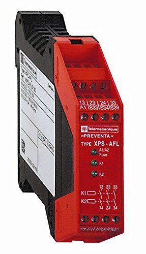
Figure 1: Front view of the Schneider Electric XPSAFL5130 Emergency Stop Module.
2. Setup and Installation
This module is designed for easy integration into industrial control panels. Follow these general guidelines for installation:
- Mounting: Securely mount the XPSAFL5130 module onto a standard 35 mm DIN rail within an appropriate enclosure. Ensure adequate ventilation around the module.
- Power Connection: Connect the supply voltage to the designated terminals. The module accepts both 24 V DC and 24 V AC power sources. Verify the voltage polarity for DC connections.
- Input Connections: Connect the emergency stop devices, safety switches, or light curtains to the module's input terminals as per your system's safety circuit design. Refer to the detailed wiring diagrams provided with the product packaging for specific terminal assignments.
- Output Connections: Connect the 3 NO direct relay opening contacts to the control circuit of the machinery or equipment that needs to be safely shut down. Ensure these connections are made to the appropriate safety-related inputs of your control system.
- Grounding: Ensure proper grounding of the module and associated equipment to prevent electrical hazards and ensure reliable operation.
- Initial Check: Before applying full power, double-check all wiring connections for correctness and security.
WARNING: Installation must be performed by qualified personnel in accordance with all local and national electrical codes and safety regulations. Incorrect wiring can lead to serious injury or death.
3. Operating Instructions
The XPSAFL5130 module operates as a safety relay, monitoring inputs from emergency stop devices and providing a safe output state when an emergency condition is detected.
- Normal Operation: When all safety inputs are closed (e.g., emergency stop button released, safety gate closed), the module's internal relays will be energized, and the 3 NO output contacts will be closed, allowing power to the controlled equipment. The LED indicators will typically show a 'safe' or 'ready' state.
- Emergency Stop Activation: If an emergency stop button is pressed, a safety gate is opened, or a light curtain is interrupted, the module detects this change in the input state. The internal relays will de-energize, and the 3 NO output contacts will open, immediately removing power from the controlled equipment. The LED indicators will change to show an 'unsafe' or 'fault' state.
- Resetting the Module: The XPSAFL5130 module typically requires a manual reset after an emergency stop event. The specific reset procedure (e.g., pressing a dedicated reset button, cycling power) should be detailed in your overall machine safety system documentation. The module's 'start type' is without control, meaning it relies on external logic for its operational start.
- LED Indicators: The module is equipped with 3 LED indicators. These LEDs provide visual feedback on the module's status, such as power supply, input status, and output status. Consult the product's technical documentation for a detailed explanation of each LED's function and fault codes.
4. Maintenance
The Schneider Electric XPSAFL5130 module is designed for reliable, long-term operation with minimal maintenance. However, periodic checks are recommended to ensure continued safety and performance:
- Visual Inspection: Regularly inspect the module for any signs of physical damage, discoloration, or loose connections. Ensure the DIN rail mounting remains secure.
- Cleaning: Keep the module free from dust and debris. Use a soft, dry cloth for cleaning. Do not use abrasive cleaners or solvents.
- Functional Testing: Periodically test the entire safety circuit, including the XPSAFL5130 module, by activating emergency stop devices and verifying that the controlled equipment safely shuts down. The frequency of these tests should comply with relevant safety standards and your facility's safety protocols.
- Wiring Integrity: Check all wiring connections to ensure they are tight and free from corrosion.
CAUTION: Disconnect all power to the module and associated equipment before performing any maintenance or inspection to prevent electrical shock.
5. Troubleshooting
If the XPSAFL5130 module or the associated safety circuit is not functioning as expected, consider the following troubleshooting steps:
- No Power/LEDs Off:
- Check the supply voltage (24 V AC/DC) at the module's power terminals.
- Verify that the power source is active and fuses/circuit breakers are not tripped.
- Module Not Resetting/Outputs Not Activating:
- Ensure all emergency stop devices are released and all safety inputs are in their safe (closed) state.
- Check for any open circuits or faults in the input wiring.
- Confirm that the manual reset procedure (if applicable to your system) has been correctly performed.
- Observe the LED indicators for any fault codes or status messages that might indicate the specific issue. Refer to the product's technical documentation for LED status interpretations.
- Outputs Not De-energizing During Emergency:
- Verify the wiring of the emergency stop devices to the module's inputs.
- Check the functionality of the emergency stop devices themselves.
- Inspect the module for internal damage (unlikely but possible).
- Intermittent Operation:
- Check for loose wiring connections or intermittent faults in safety devices.
- Ensure the operating environment is within specified temperature and humidity ranges.
If troubleshooting steps do not resolve the issue, contact Schneider Electric technical support or a qualified service technician.
6. Specifications
| Manufacturer | Schneider Electric |
| Item Model Number | XPSAFL5130 |
| Product Dimensions | 12.1 x 10.5 x 3 cm |
| Weight | 250 g |
| ASIN | B003UQV2SA |
| Supply Voltage | 24 V DC (±15-10%), 24 V AC (±15-10%) |
| Current Consumption | 30 mA at 24 V AC (power supply) |
| Output Type | Direct relay opening, 3 NO contacts |
| Auxiliary Contacts | 0 |
| Local Signal | 3 LED indicators |
| Mounting | 35 mm DIN Rail |
| Discontinued by Manufacturer | No |
| Date First Available | 12 April 2015 |
| Guaranteed Software Updates Until | Unknown |
7. Warranty and Support
Specific warranty information for the Schneider Electric XPSAFL5130 module is not provided in this document. For details regarding warranty coverage, terms, and conditions, please refer to the official documentation included with your product purchase or contact Schneider Electric directly.
For technical support, service, or further inquiries, please visit the official Schneider Electric website or contact their customer service department. Ensure you have your product model number (XPSAFL5130) and any relevant purchase information ready when seeking support.