De-Sta-Co 2010-UR
DE-STA-CO 2010-UR Vertical Hold-Down Action Clamp User Manual
1. Introduction
This manual provides essential information for the safe and effective use of the DE-STA-CO 2010-UR Vertical Hold-Down Action Clamp. This robust toggle clamp is designed for various workholding applications in manufacturing and industrial settings. It features an enhanced design with increased capacity, a longer handle for improved hand clearance, and an extended clamp arm, making it a versatile and powerful tool for securing workpieces.
2. Safety Information
Always observe the following safety precautions when operating the DE-STA-CO 2010-UR clamp:
- Ensure the clamp is securely mounted to a stable surface before use.
- Do not exceed the rated holding capacity of the clamp.
- Keep hands and fingers clear of moving parts during operation to prevent pinching.
- Regularly inspect the clamp for wear, damage, or loose components. Do not use a damaged clamp.
- Wear appropriate personal protective equipment (PPE) as required by your work environment.
- Ensure the workpiece is properly seated and secured before beginning any work.
3. Product Components
The DE-STA-CO 2010-UR Vertical Hold-Down Action Clamp consists of several key components that work together to provide secure workholding. Refer to the image below for a visual representation of the clamp.
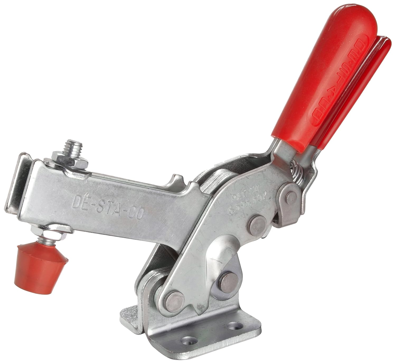
This image displays the complete DE-STA-CO 2010-UR Vertical Hold-Down Action Clamp. Key components include the red handle for operation, the main body of the clamp, the clamping arm, and the spindle assembly with a red rubber tip for contacting the workpiece. The base plate, visible at the bottom, is used for mounting the clamp to a fixture or workbench.
- Handle: The red grip handle used to actuate the clamping mechanism.
- Clamp Arm: The movable arm that extends to hold the workpiece.
- Base Plate: The mounting surface with pre-drilled holes for secure attachment.
- Spindle Assembly: Consists of a threaded spindle and a rubber-tipped bolt, allowing for fine adjustment of clamping pressure and workpiece contact.
- Linkage System: The internal mechanism that provides the toggle action for powerful clamping.
4. Setup and Installation
Proper installation is crucial for the safe and effective operation of your DE-STA-CO 2010-UR clamp.
4.1 Mounting the Clamp
- Identify a stable and appropriate mounting surface (e.g., workbench, fixture plate) that can withstand the clamping forces.
- Position the clamp's base plate on the desired mounting location. The 2010-UR model is designed to bolt up to legacy model 210 mounting patterns.
- Mark the locations for drilling mounting holes if necessary, using the base plate as a template.
- Drill appropriate pilot holes for your chosen fasteners.
- Secure the clamp to the surface using bolts, nuts, and washers of suitable size and strength. Ensure all fasteners are tightened securely.
4.2 Adjusting the Spindle
The spindle assembly allows for precise adjustment to accommodate different workpiece heights and apply optimal clamping force.
- With the clamp in the open position, place the workpiece on your fixture.
- Loosen the lock nut on the spindle assembly.
- Adjust the spindle bolt by rotating it until the rubber tip makes firm contact with the workpiece when the clamp arm is brought down.
- Ensure the clamp arm reaches its full over-center position when engaged, providing a positive lock.
- Tighten the lock nut securely against the clamp arm to prevent the spindle from shifting during operation.
5. Operating Instructions
Follow these steps for proper operation of your DE-STA-CO 2010-UR clamp:
5.1 Engaging the Clamp
- Place the workpiece securely on the workholding fixture.
- Ensure the spindle is adjusted correctly to contact the workpiece.
- Grasp the red handle and push it downwards until the clamp arm moves into position and the linkage system locks into its over-center position. This action applies the holding force.
- Verify that the workpiece is firmly held and does not shift.
5.2 Releasing the Clamp
- Grasp the red handle and pull it upwards.
- Continue pulling until the clamp arm lifts clear of the workpiece and the linkage system is fully disengaged.
- Remove the workpiece.
6. Maintenance
Regular maintenance ensures the longevity and reliable performance of your DE-STA-CO clamp.
- Inspection: Periodically inspect all pivot points, pins, and the base plate for wear, corrosion, or damage. Check for any loose fasteners.
- Lubrication: Apply a light machine oil or grease to all pivot points and moving parts every few weeks, or more frequently in high-use environments. This reduces friction and prevents rust.
- Cleaning: Keep the clamp clean and free of debris, chips, and dust. A clean clamp operates more smoothly and efficiently.
- Spindle Condition: Check the condition of the rubber tip on the spindle. Replace if it shows signs of excessive wear or damage to maintain proper grip.
7. Troubleshooting
This section addresses common issues you might encounter with your DE-STA-CO 2010-UR clamp.
| Problem | Possible Cause | Solution |
|---|---|---|
| Clamp does not hold workpiece securely. | Spindle not adjusted correctly; clamp not fully engaged; worn spindle tip; clamp capacity exceeded. | Adjust spindle for firm contact; ensure handle reaches over-center position; replace worn spindle tip; verify workpiece weight/force is within clamp's capacity. |
| Difficulty engaging or disengaging clamp. | Lack of lubrication; debris in linkage; bent components. | Lubricate pivot points; clean linkage system; inspect for and replace any bent or damaged parts. |
| Clamp feels loose or wobbly. | Loose mounting bolts; worn pivot pins. | Tighten all mounting bolts; inspect and replace worn pivot pins if necessary. |
8. Specifications
The following table outlines the key specifications for the DE-STA-CO 2010-UR Vertical Hold-Down Action Clamp:
| Specification | Value |
|---|---|
| Model Number | 2010-UR |
| Brand | De-Sta-Co |
| Material | Alloy Steel |
| Product Dimensions (L x W x H) | 15 x 9.3 x 2.7 inches |
| Item Weight | 2.85 Pounds |
| Color | Red (handle) |
| Style | Modern |
8.1 Key Features
- New generation toggle clamp with over 2 times the capacity of legacy models.
- Longer handle with greater hand clearance for improved ergonomics.
- Longer clamp arm for increased reach and versatility.
- Bolts up to legacy model 210 mounting patterns for easy integration.
8.2 Technical Drawings
Detailed dimensions are provided in the following technical drawings:


9. Warranty and Support
For information regarding the product warranty, please refer to the official DE-STA-CO website or contact their customer support directly. Keep your purchase receipt as proof of purchase.
For technical assistance, spare parts, or further inquiries, please contact DE-STA-CO customer service through their official channels. Provide the model number (2010-UR) when seeking support to ensure accurate assistance.
Ask a question about this manual
Ask about setup, troubleshooting, compatibility, parts, safety, or missing instructions. Manuals+ will review the question and use this page’s manual context to help answer it.