1. Introduction
This manual provides essential information for the installation, operation, and maintenance of the Honeywell RM7890A1015 On-Off Primary Burner Control. This microprocessor-based control is designed for automatically fired gas, oil, or combination fuel single burner applications, offering advanced safety and functional capabilities beyond conventional controls.
2. Safety Information
WARNING: Fire or Explosion Hazard. Property damage, severe injury, or death can result. Specific installation and operational requirements must be performed each time this control is installed to ensure safe burner operation.
Always consult local codes and regulations before installation. Ensure power is disconnected before servicing the unit or any associated components.

Figure 1: Rear view of the Honeywell RM7890A1015 Burner Control. This image displays the wiring terminals (G, L2(N), L1, ALARM, CONTROLLER & LIMITS, INTERMITTENT PILOT, MAIN FUEL VALVE, IGNITOR, FLAME SENSOR, UNUSED) and electrical specifications (120 VAC 50/60 Hz). It also features prominent warning labels regarding fire or explosion hazards, emphasizing the need for proper installation and operation. The model number "RM7890 A 1015" and serial number "1840Q65785" are visible.
3. Product Overview
The Honeywell RM7890A1015 is an advanced primary burner control unit designed to manage and monitor burner operations. Its key features include:
- Automatic burner sequencing for efficient and controlled startup and shutdown.
- Integrated flame supervision for enhanced safety, continuously monitoring the presence of flame.
- Comprehensive system status indication through LED indicators.
- Built-in system or self-diagnostics and troubleshooting capabilities to identify operational issues.
- Five distinct LEDs providing sequence information for quick status checks.
- Interchangeable plug-in flame amplifiers for flexible configuration and serviceability.
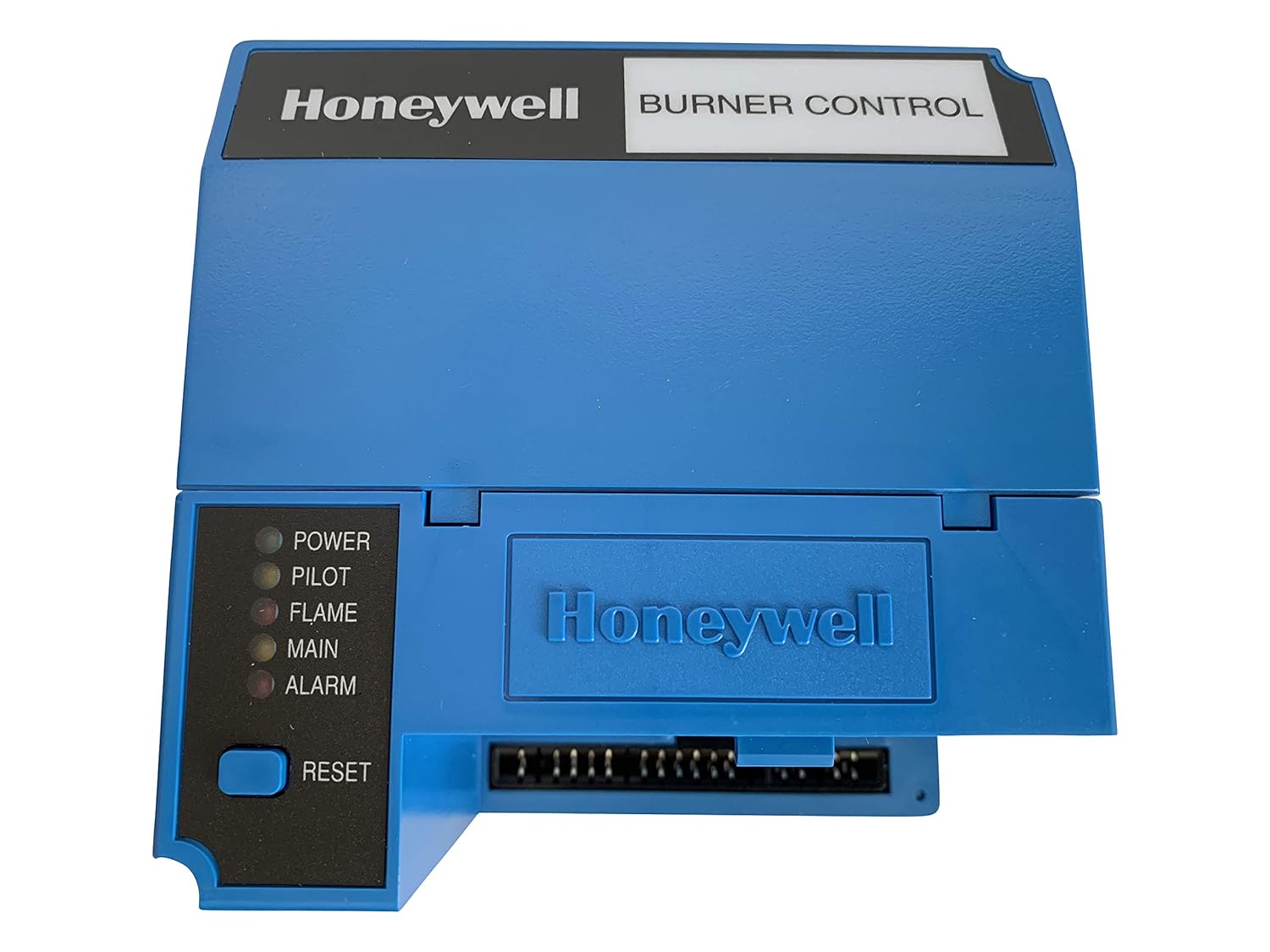
Figure 2: Front view of the Honeywell RM7890A1015 Burner Control. This panel features the Honeywell logo and "BURNER CONTROL" label. On the left side, there are five LED indicators labeled POWER, PILOT, FLAME, MAIN, and ALARM, along with a RESET button. These indicators provide visual feedback on the control's operational status.
4. Setup and Installation
Proper installation is crucial for the safe and effective operation of the RM7890A1015. Installation should only be performed by qualified personnel.
4.1. Components Required
- A compatible subbase (sold separately) is required for mounting and electrical connections.
- An appropriate plug-in flame amplifier must be installed into the control unit.
4.2. Wiring
Refer to the wiring diagram on the back of the unit (as shown in Figure 1) and consult the specific installation instructions provided with the subbase and amplifier for detailed wiring procedures. Ensure all connections adhere to local electrical codes and manufacturer specifications. The unit operates on 120 VAC, 50/60 Hz.
5. Operating Instructions
The RM7890A1015 automates the burner sequencing process. Understanding the LED indicators is key to monitoring its operation.
5.1. Power-Up Sequence
- Ensure all wiring is correct and secure, and the subbase and amplifier are properly installed.
- Apply power to the control system. The POWER LED should illuminate, indicating the unit is receiving power.
- The control will initiate its pre-purge and ignition sequence according to its programmed cycle.
- Observe the PILOT and FLAME LEDs for successful pilot and main flame establishment.
- Once the main flame is established and stable, the MAIN LED will illuminate, indicating normal burner operation.
5.2. Resetting the Control
In case of a lockout condition (typically indicated by the ALARM LED), press the RESET button on the front panel to clear the fault and attempt a restart. Always investigate the cause of a lockout before resetting to prevent recurrence or potential hazards.
6. Maintenance
The Honeywell RM7890A1015 is designed for reliable operation with minimal routine maintenance. However, periodic checks are recommended to ensure optimal performance and safety.
- Periodically inspect wiring connections for tightness, corrosion, and signs of wear.
- Keep the control unit clean and free from dust, debris, and moisture.
- Ensure proper ventilation around the control to prevent overheating.
- For any internal servicing or component replacement, contact a qualified service technician.
Regular system checks by a qualified technician are recommended to ensure continued safe and efficient operation of the entire burner system.
7. Troubleshooting
The RM7890A1015 features self-diagnostics to assist in troubleshooting operational issues. The LED indicators on the front panel provide critical status information.
7.1. LED Indicators
The five LEDs on the front panel (Figure 2) provide the following status indications:
- POWER: Illuminates when the unit is receiving electrical power.
- PILOT: Illuminates when the pilot flame is established during the ignition sequence.
- FLAME: Illuminates when the main flame is detected by the flame sensor.
- MAIN: Illuminates during normal main burner operation.
- ALARM: Illuminates to indicate a lockout condition or fault within the system.
If the ALARM LED illuminates, note the sequence of events leading to the lockout. Options such as a first-out expanded annunciator (if installed) can provide more detailed fault codes. Consult the system's overall diagnostic information and the specific fault codes for resolution. If the issue persists, contact a qualified service technician.
8. Specifications
| Feature | Detail |
|---|---|
| Model Number | RM7890A1015 |
| Product Dimensions | 8 x 7 x 7 inches |
| Weight | 2 Pounds |
| Manufacturer | Honeywell |
| First Available | March 18, 2010 |
| ASIN | B003CVZ8VU |
| Electrical Rating | 120 VAC, 50/60 Hz |
9. Warranty and Support
For warranty information and technical support regarding your Honeywell RM7890A1015 On-Off Primary Burner Control, please contact Honeywell customer service or visit the official Honeywell website. Keep your purchase receipt and model number (RM7890A1015) readily available when seeking support.
Note: The serial number of the item you receive may vary from the item pictured here.