
1. Introduction
This manual provides essential information for the safe and efficient installation, operation, and maintenance of the Hydromatic SP50M1 Submersible Sewage Ejector Pump. Please read this manual thoroughly before attempting to install or operate the pump. Retain this manual for future reference.
The Hydromatic SP50M1 is a robust 1/2 HP, 115 Volt, single-phase cast iron submersible pump designed for handling sewage and effluent in residential and light commercial applications. It features a 2-inch NPT discharge and is capable of handling solids up to 1-1/2 inches.
2. Safety Information
WARNING: Risk of Electric Shock. Always disconnect power before servicing the pump or basin.
WARNING: Risk of Injury. Do not operate the pump in an explosive atmosphere or pump flammable liquids.
- Ensure all electrical connections are made by a qualified electrician and comply with local codes.
- The pump must be properly grounded to prevent electrical shock.
- Do not run the pump dry. Running without liquid can cause severe damage and void the warranty.
- Wear appropriate personal protective equipment (PPE) when handling the pump or working in the basin.
- Keep hands and feet clear of the impeller area when power is connected.
3. Product Overview and Components
The Hydromatic SP50M1 is constructed from durable cast iron, designed for longevity and reliable performance in demanding sewage applications. Key components include the motor housing, impeller, volute, and power cord.

Figure 1: Front view of the Hydromatic SP50M1 pump, showing the main body, discharge port, and power cord.

Figure 2: Side view of the Hydromatic SP50M1 pump, highlighting the robust cast iron construction and handle.
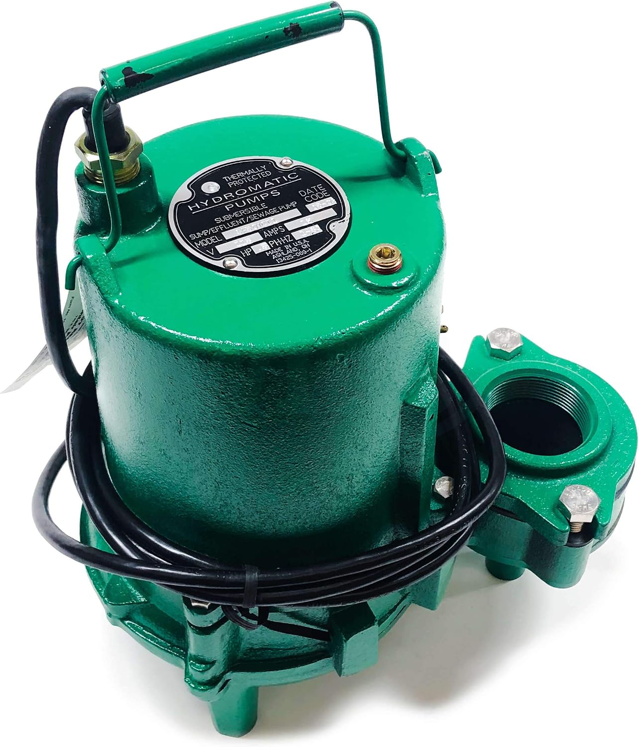
Figure 3: Top view of the pump, showing the motor housing and the identification label.

Figure 4: Close-up of the pump's identification label, displaying model number, electrical ratings, and manufacturer information.
4. Setup and Installation
4.1 Pre-Installation Checks
- Verify that the power supply matches the pump's requirements (115 Volt, 1 Phase).
- Ensure the sewage basin is clean and free of debris.
- Confirm the basin size is adequate for the pump's operation and liquid volume.
- Inspect the pump for any shipping damage.
4.2 Electrical Connections
- The pump is equipped with a 10-foot cord and a grounded plug. Connect it to a properly grounded 115V, 15 Amp circuit.
- A dedicated circuit is recommended.
- For manual operation, an external control panel or switch is required to activate and deactivate the pump.
- All wiring must comply with the National Electrical Code (NEC) and local codes.
4.3 Discharge Piping
- Connect 2-inch NPT discharge piping to the pump's outlet.
- Install a check valve in the discharge line to prevent backflow into the basin.
- Use a union in the discharge line for easy pump removal.
- Ensure all connections are watertight.
4.4 Pump Placement
- Lower the pump into the basin, ensuring it rests on a solid, level surface.
- Ensure the pump is positioned so that the intake is clear of any obstructions.
- The power cord should be routed to prevent kinking or damage.
5. Operating Instructions
The Hydromatic SP50M1 is a manual pump, meaning it does not have an integrated float switch for automatic operation. It requires an external control mechanism or manual activation.
5.1 Initial Startup
- After installation, ensure the basin contains liquid to prevent dry running.
- Activate the pump using the external control switch.
- Observe the pump's operation for any unusual noises or vibrations.
- Verify that water is being discharged properly and that there are no leaks in the piping.
5.2 Normal Operation
- The pump should run smoothly, evacuating the liquid from the basin.
- Avoid continuous operation for extended periods without proper cooling.
- Monitor the liquid level in the basin to prevent the pump from running dry.
5.3 Shutting Down
- Deactivate the pump using the external control switch.
- For extended periods of non-use, disconnect the pump from the power supply.
6. Maintenance
CAUTION: Always disconnect power to the pump before performing any maintenance.
6.1 Regular Inspection (Monthly)
- Check the power cord for any signs of damage, fraying, or insulation breakdown.
- Inspect the pump housing for cracks or corrosion.
- Ensure the basin is free of excessive debris that could clog the pump intake.
- Verify that the check valve is functioning correctly.
6.2 Cleaning
- If the pump's performance decreases, it may be due to impeller or volute clogging.
- Remove the pump from the basin and carefully clean any accumulated debris from the impeller and volute area.
- Do not use harsh chemicals that could damage pump components.
6.3 Winterization (if applicable)
- If the pump is installed in an area subject to freezing temperatures and will not be used, remove it from the basin.
- Clean the pump thoroughly and store it in a dry, frost-free location.
7. Troubleshooting
Before attempting any troubleshooting, ensure the power supply to the pump is disconnected.
| Problem | Possible Cause | Solution |
|---|---|---|
| Pump does not run | No power to pump Thermal overload tripped Clogged impeller | Check circuit breaker/fuse Allow pump to cool, then reset Clear debris from impeller |
| Pump runs but no water discharges or low flow | Discharge line clogged Check valve stuck closed Impeller damaged or clogged Air lock | Clear obstruction Inspect/replace check valve Clear/replace impeller Ensure pump is fully submerged and vent air |
| Pump runs continuously | External control switch stuck on Backflow through discharge line | Inspect/replace external switch Inspect/replace check valve |
| Excessive noise or vibration | Debris in pump Worn bearings Pump not sitting level | Clear debris Contact service technician Ensure pump is on a stable, level surface |
8. Specifications
| Feature | Specification |
|---|---|
| Model | SP50M1 |
| Brand | HYDROMATIC |
| Horsepower | 0.5 HP |
| Voltage | 115 Volts |
| Phase | 1 Phase |
| Amperage Capacity | 12 Amps |
| Material | Cast Iron |
| Style | Submersible |
| Maximum Flow Rate | 140 Gallons Per Minute |
| Solids Handling | 1-1/2 inches |
| Discharge Size | 2 inches NPT |
| RPM | 1750 RPM |
| Cord Length | 10 Feet |
| Item Weight | 61 Pounds |
| UPC | 619872017933 |
| Part Number | SP50MCI1 |
9. Warranty and Support
9.1 Warranty Information
For detailed warranty information, please refer to the official Hydromatic warranty statement provided with your purchase or visit the Hydromatic website. Keep your proof of purchase for warranty claims.
9.2 Customer Support
If you require technical assistance, replacement parts, or have questions regarding your Hydromatic SP50M1 pump, please contact Hydromatic customer service. Contact information can typically be found on the manufacturer's official website or on the product packaging.
Manufacturer: Hydromatic