
1. Introduction
Thank you for choosing the Cooper 7513W-BOX 15-Amp 3-Way Rocker Switch. This device is designed for reliable control of lighting or other electrical loads in residential and light commercial environments. It features a durable thermoplastic construction and a quiet rocker actuator for comfortable operation. This manual provides essential information for safe installation, operation, and maintenance of your new switch.
A 3-way switch allows control of a single light fixture from two different locations. This switch is rated for 15 Amps and operates on 120-277 Volts AC.
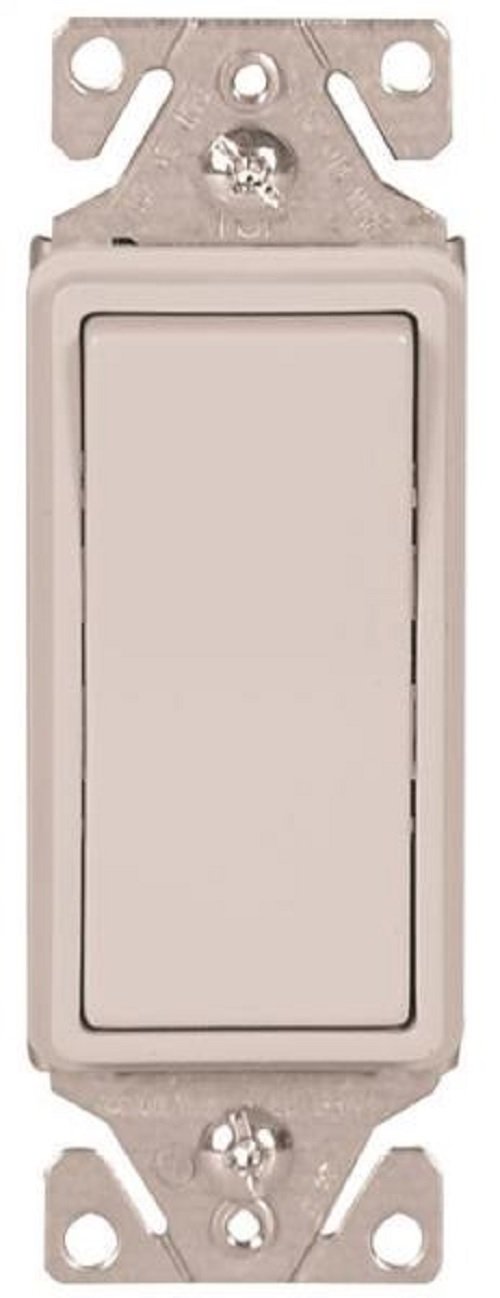
Image 1: Cooper 7513W-BOX 15-Amp 3-Way Rocker Switch. This image displays the front view of the white rocker switch, highlighting its clean design and the rocker mechanism.
2. Important Safety Information
WARNING: To avoid fire, shock, or death, turn off power at the circuit breaker or fuse box and test that the power is off before wiring. Always use appropriate safety precautions when working with electrical wiring.
- Installation should be performed by a qualified electrician or a person with a thorough understanding of electrical wiring and building codes.
- Do not install if the product appears damaged.
- Ensure all wire connections are secure and properly insulated.
- This device is intended for indoor use only.
- Adhere to all national and local electrical codes.
- Do not exceed the maximum electrical ratings of 15 Amps and 120-277 Volts AC.
3. Package Contents
Verify that all components are present before beginning installation:
- 1x Cooper 7513W-BOX 15-Amp 3-Way Rocker Switch
- 1x Metal Mounting Strap (pre-attached)
- Installation Screws (typically included with switch or wall plate)
Note: A wall plate is sold separately and is not included with the switch.
4. Installation (Setup)
This section outlines the steps for installing your 3-way rocker switch. A 3-way switch system requires two 3-way switches to control one light fixture from two locations. It involves traveler wires and a common wire.
4.1 Tools Required
- Screwdriver (Phillips and/or Flathead)
- Wire Strippers/Cutters
- Voltage Tester
- Electrical Tape
4.2 Wiring Diagram Overview
A 3-way switch has three terminals plus a ground terminal. One terminal is the common terminal (often darker or labeled "COMMON"), and the other two are traveler terminals. The common terminal on the first switch connects to the power source (hot wire), and the common terminal on the second switch connects to the light fixture. The two traveler terminals on each switch connect to each other.
Note: Due to the complexity of 3-way wiring, it is highly recommended to consult a qualified electrician or refer to detailed wiring diagrams specific to your home's electrical setup. The following steps are general guidelines.
4.3 Installation Steps
- Turn Off Power: Locate the circuit breaker or fuse that supplies power to the switch location and turn it OFF. Verify power is off using a voltage tester.
- Remove Old Switch: Carefully remove the existing wall plate and unscrew the old switch from the electrical box. Disconnect the wires, noting which wire was connected to which terminal (especially the common wire).
- Identify Wires:
- Ground Wire: Bare copper or green insulated wire. Connects to the green screw terminal on the new switch.
- Common Wire: Often a darker colored screw terminal on the old switch. This is the incoming hot wire (from power source) or the outgoing hot wire (to the light fixture). Mark this wire for identification.
- Traveler Wires: The remaining two wires. These carry power between the two 3-way switches.
- Connect New Switch:
- Connect the ground wire to the green screw terminal.
- Connect the identified common wire to the common (darker) screw terminal on the new switch.
- Connect the two traveler wires to the remaining two screw terminals. The order of traveler wires does not matter.
- For push-in terminals: Ensure wires are stripped to the correct length (usually 1/2 inch) and insert firmly into the designated holes.
- Mount Switch: Gently fold the wires into the electrical box. Secure the switch to the electrical box using the provided mounting screws.
- Install Wall Plate: Attach the new or existing wall plate over the switch.
- Restore Power: Turn the power back ON at the circuit breaker.
- Test Operation: Test the switch from both locations to ensure proper functionality.
For visual guidance, it is recommended to search for "3-way switch wiring diagram" online or consult a professional.
5. Operating Instructions
The Cooper 7513W-BOX is a simple rocker-style switch. To operate:
- To Turn ON: Press the top portion of the rocker switch.
- To Turn OFF: Press the bottom portion of the rocker switch.
In a 3-way setup, the state of the light (ON or OFF) can be changed by toggling either of the two connected 3-way switches.
6. Care and Maintenance
The Cooper 7513W-BOX rocker switch requires minimal maintenance.
- Cleaning: To clean the switch and wall plate, first turn off power at the circuit breaker. Use a soft, damp cloth with a mild household cleaner. Avoid abrasive cleaners, solvents, or harsh chemicals, as these can damage the finish. Ensure the switch is completely dry before restoring power.
- Inspection: Periodically inspect the switch and wall plate for any signs of damage, cracks, or discoloration. If any damage is observed, turn off power and replace the switch.
- No User-Serviceable Parts: There are no user-serviceable parts inside the switch. Do not attempt to disassemble the unit.
7. Troubleshooting
If you experience issues with your Cooper 7513W-BOX switch, refer to the following common problems and solutions:
| Problem | Possible Cause | Solution |
|---|---|---|
| Light does not turn ON/OFF from either switch. | No power to the circuit; loose wire connection; faulty switch. |
|
| Light only turns ON/OFF from one switch. | Incorrect 3-way wiring; loose traveler wire connection. |
|
| Switch feels loose or wobbly. | Mounting screws are loose. | Turn off power, remove wall plate, and tighten the mounting screws securing the switch to the electrical box. |
If the problem persists after attempting these solutions, contact a qualified electrician.
8. Specifications
| Feature | Detail |
|---|---|
| Model Number | 7513W-BOX |
| Brand | Cooper (EATON) |
| Current Rating | 15 Amps |
| Operating Voltage | 120-277 Volts AC |
| Circuit Type | 3-Way |
| Actuator Type | Rocker |
| Color | White |
| Material | Thermoplastic body, Metal strap |
| Dimensions (L x W x H) | 9.18 x 3.9 x 4.5 inches |
| Item Weight | 2.4 ounces |
| Connectivity Protocol | X-10 (Note: Typically for smart modules, not basic switches) |
| International Protection Rating | IP00 |
| Certifications | CUL/UL Listed |
Note on Material: The product description mentions "thermoplastic" while specifications list "Metal". The switch body is typically thermoplastic, with a metal mounting strap.
Note on Connectivity Protocol: While "X-10" is listed, this is a standard mechanical rocker switch. The X-10 protocol typically applies to smart home modules, not the switch itself. This specification might be a data entry error or refer to compatibility with an external X-10 module.
9. Warranty and Support
For warranty information and technical support, please refer to the official Cooper (EATON) website or contact their customer service directly. Specific warranty terms may vary by region and purchase date.
Manufacturer: EATON
Brand: Cooper
Website: www.eaton.com (or search for Cooper Wiring Devices)
Customer Service: Refer to the manufacturer's website for contact details.