1. Introduction
This manual provides essential information for the safe and efficient installation, operation, and maintenance of the Homematic 71328 HMW-IO-12-Sw7-DR RS485 I/O Module. This device is designed for integration into Homematic wired systems, offering 12 digital inputs and 7 relay outputs for various automation tasks. Please read this manual thoroughly before using the device.
2. Safety Instructions
Warning: Electrical equipment should only be installed and mounted by a qualified electrician. Failure to observe these instructions may result in fire, electric shock, or other injuries.
- Ensure the power supply is disconnected before installation or maintenance.
- The device is designed for indoor use only.
- Do not open the device. It contains no user-serviceable parts.
- Protect the device from moisture, dust, and direct sunlight.
- Observe the maximum load specifications for the relay outputs.
3. Package Contents
Verify that all items are present and undamaged upon unpacking:
- 1x Homematic HMW-IO-12-Sw7-DR RS485 I/O Module (Model 71328)
- 1x Instruction Manual (German, English)
4. Product Overview
The Homematic HMW-IO-12-Sw7-DR is a versatile RS485 I/O module designed for DIN rail mounting. It provides 12 digital inputs and 7 switching relay outputs, enabling the integration of conventional switches, sensors, and loads into a Homematic wired smart home system. The module facilitates robust and reliable communication within the RS485 bus network.
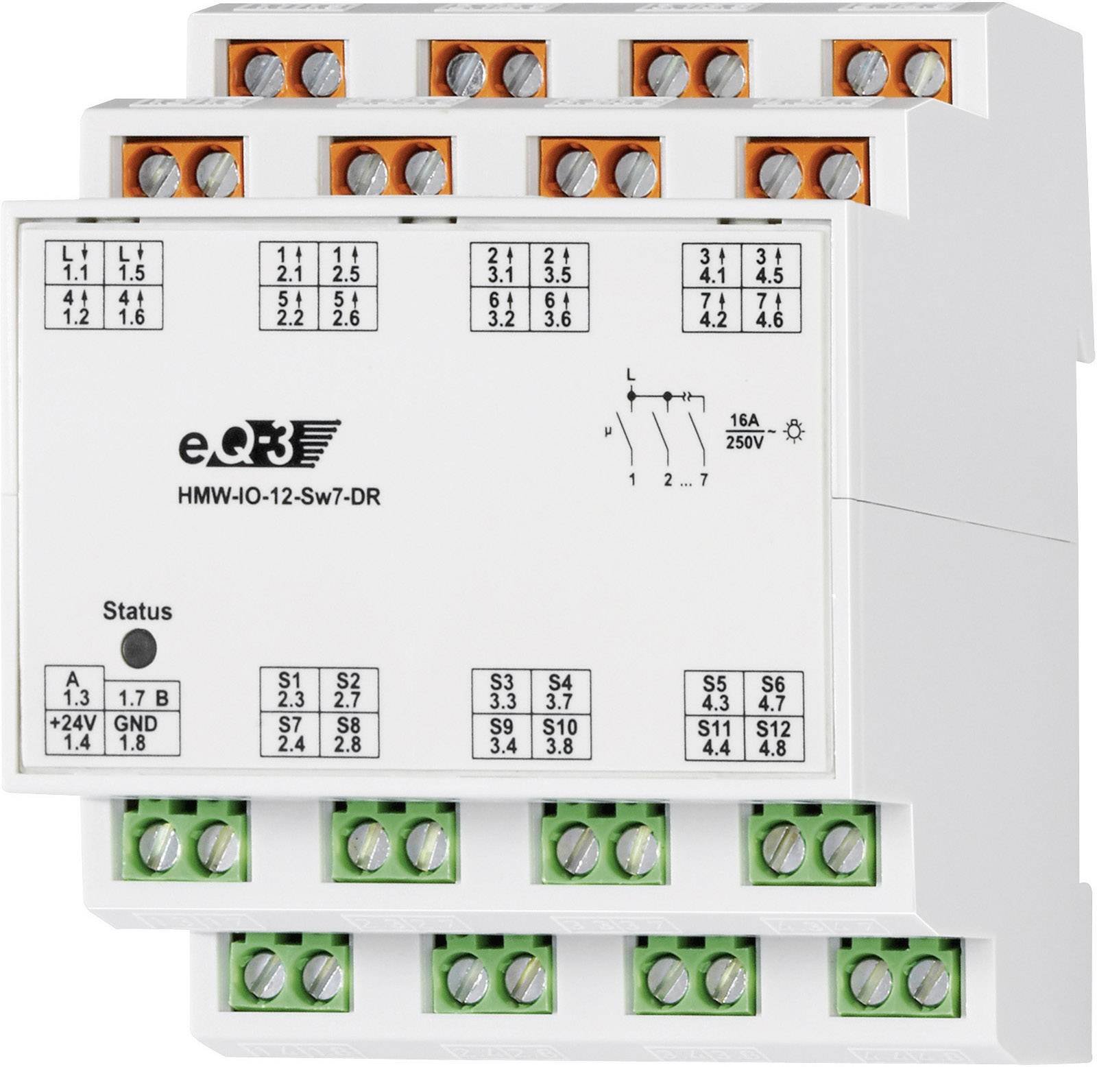
Figure 1: Front view of the Homematic 71328 HMW-IO-12-Sw7-DR RS485 I/O Module. This image shows the compact design suitable for DIN rail installation, with terminals for inputs and outputs.
5. Installation and Setup
Prerequisites:
- A 24V DC power supply is required for the module's operation.
- A Homematic LAN Gateway or central control unit (e.g., CCU3) is necessary for configuration and integration into the Homematic system. The module cannot be used meaningfully without a central unit.
- DIN rail for mounting.
5.1 Mounting
Mount the module onto a standard DIN rail in an electrical distribution box or suitable enclosure. Ensure adequate ventilation and clearance around the device.
5.2 Wiring
Power Supply (24V DC): Connect the 24V DC power supply to the designated terminals on the module.
RS485 Bus Connection: Connect the module to the Homematic RS485 bus network according to the system's wiring diagram. Ensure correct polarity.
Inputs (24V): The 12 inputs are designed for 24V operation. Connect conventional buttons or sensors that provide a 24V signal to these inputs. The 24V supply for these inputs is provided by the module itself.
Outputs (230V AC Relays): The 7 relay outputs are designed to switch 230V AC loads.
- Connect the phase (L) to the common terminal for the outputs.
- Connect the individual loads to the switched output terminals.
- Important: The relay outputs are not potential-free. There is only one common connection for the phase, which is then switched through all relays.
- Maximum Load: Each individual relay can handle a maximum load of 16A. However, the total combined load across all relays must not exceed 16A. For example, if all 7 relays are used equally, each relay can be loaded with approximately 2.2A.
5.3 Learning-in Process
Once wired, the module must be "learned-in" to your Homematic central control unit (e.g., CCU3). Refer to your central unit's manual for detailed instructions on adding new wired devices. This process typically involves putting the central unit into learning mode and then activating the learning function on the module (e.g., by pressing a system button if available, or through software configuration).
6. Operating Instructions
After successful learning-in, the Homematic 71328 module's inputs and outputs can be configured and controlled via your Homematic central unit. You can create programs and direct associations to automate functions based on input signals (e.g., a button press) and control connected loads via the relay outputs.
- Inputs: The 12 inputs can be used to detect states from conventional switches, push-buttons, or sensors. These states can trigger actions within your Homematic system.
- Outputs: The 7 relay outputs can switch connected 230V AC loads (e.g., lights, pumps, valves) on or off based on programmed logic or manual commands from the central unit.
7. Maintenance
The Homematic 71328 module is designed for maintenance-free operation. However, periodic checks are recommended:
- Ensure all wiring connections are secure.
- Keep the device free from dust and dirt. Use a dry, soft cloth for cleaning.
- Do not use aggressive cleaning agents.
8. Troubleshooting
If you encounter issues with your Homematic 71328 module, consider the following:
- Device not responding:
- Check the 24V DC power supply.
- Verify the RS485 bus connection and polarity.
- Ensure the module is correctly learned-in to the central unit.
- Outputs not switching:
- Check the 230V AC supply to the common terminal of the outputs.
- Verify the load connections.
- Ensure the total load does not exceed 16A and individual relay loads do not exceed 16A.
- Check the programming in your Homematic central unit.
- Inputs not registering:
- Verify the 24V signal from the connected button/sensor.
- Check the wiring to the input terminals.
- Ensure the input is correctly configured in the central unit.
For further assistance, consult the Homematic central unit manual or contact Homematic support.
9. Specifications
| Model Number | 71328 |
| Manufacturer | eQ-3 AG |
| Inputs | 12 digital inputs (24V) |
| Outputs | 7 relay outputs (230V AC, non-potential-free) |
| Max. Current per Relay | 16 A |
| Max. Total Current | 16 A (across all 7 relays) |
| Max. Switching Capacity | 3680 W (at 230V AC) |
| Power Supply | 24V DC |
| Dimensions (L x W x H) | 3.61 x 8.71 x 7.19 cm |
| Weight | 108.86 grams |
| Mounting | DIN rail |
| Color | White |
| Country of Origin | Germany |
10. Warranty and Support
This product is covered by the manufacturer's standard warranty. For specific warranty terms and conditions, please refer to the documentation provided with your purchase or visit the Homematic IP website. For technical support, troubleshooting assistance, or spare parts inquiries, please contact Homematic IP customer service or your authorized dealer.
Availability of spare parts: Information unavailable.