1. Product Overview
The Cooler Master Elite 360 is a versatile mid/mini-tower computer chassis designed to accommodate both micro-ATX and ATX motherboards. It features a modern black design, offering a compact yet quality build suitable for various environments. The Elite 360 is engineered to maintain a quiet operational environment while providing flexible ventilation options, including support for 80mm bottom and rear fans, and 120mm top and side fans, ensuring optimal airflow for system components.
Key Features:
- Motherboard Compatibility: Supports ATX and micro-ATX motherboards within a compact enclosure.
- Flexible Placement: Can be positioned vertically or horizontally to optimize space utilization.
- Cable Management: Designed with features for improved cable routing and internal neatness.
- Tool-Free Drive Bays: Facilitates quick and easy installation of storage drives.
- Accessible I/O Panel: Top-mounted I/O panel provides convenient access to ports.

Figure 1.1: Front-side view of the Cooler Master Elite 360 chassis. This image displays the overall exterior design, including the front panel with drive bays and I/O ports, and the side panel with ventilation grilles.

Figure 1.2: The Cooler Master Elite 360 chassis shown in a horizontal desktop orientation. This illustrates the case's versatility for different setups.
2. Setup and Installation
This section provides instructions for installing core components into your Cooler Master Elite 360 chassis. Ensure your system is powered off and disconnected from the mains before beginning any installation.
2.1. Opening the Chassis
- Place the chassis on a flat, stable surface.
- Locate the thumbscrews on the rear of the chassis securing the side panel.
- Unscrew the thumbscrews and carefully slide the side panel backward, then lift it away from the chassis.

Figure 2.1: Internal view of the chassis with the side panel removed. This image illustrates the spacious interior for component installation, including drive bays and motherboard mounting area.
2.2. Motherboard Installation
- Install the I/O shield provided with your motherboard into the corresponding opening at the rear of the chassis.
- Align your ATX or micro-ATX motherboard with the pre-installed standoffs inside the chassis.
- Secure the motherboard using the appropriate screws. Do not overtighten.
2.3. Power Supply Installation
The Elite 360 supports standard ATX power supplies. The power supply mounting location is at the front of the chassis.
- Position the power supply in its designated bay at the front of the chassis.
- Secure the power supply using screws from the rear of the chassis.
- Route power cables through the designated cable management openings to maintain airflow and neatness.
2.4. Drive Installation (HDD/SSD/Optical Drives)
The chassis features tool-free drive bays for 5.25-inch optical drives and 3.5-inch hard disk drives.
- 5.25-inch Drives: Remove the front panel bay cover. Slide the optical drive into the bay until it clicks into place, securing it with the tool-free mechanism.
- 3.5-inch Drives: Slide the hard drive into an available 3.5-inch bay. The tool-free mechanism will secure it.
- 2.5-inch Drives (SSD): Adapters (not included) may be required to install 2.5-inch SSDs into 3.5-inch bays.
2.5. Expansion Card Installation
- Remove the necessary expansion slot covers from the rear of the chassis.
- Insert your expansion card (e.g., graphics card, sound card) into the appropriate slot on the motherboard.
- Secure the card with the provided screw or retention clip.
- Note: Due to the compact design and front-mounted power supply, some longer graphics cards may not fit. Verify your graphics card dimensions against the chassis's internal clearance before installation.

Figure 2.2: Rear view of the chassis. This image highlights the expansion slots, I/O shield opening, and power supply mounting area.
3. Operating Instructions
Once all components are installed and cables are connected, you can begin operating your system.
3.1. Powering On/Off
- Connect the power cable to the power supply and a wall outlet.
- Press the power button located on the front I/O panel to turn on your system.
- To turn off, use the operating system's shutdown procedure or press and hold the power button for several seconds for a forced shutdown (not recommended for regular use).
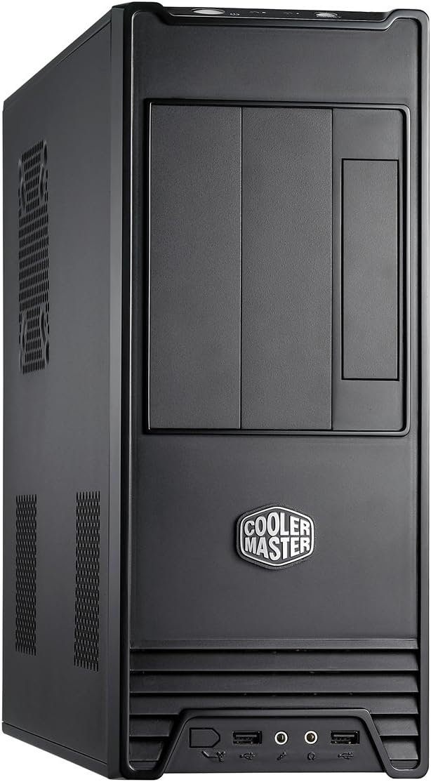
Figure 3.1: Front panel detail. This image shows the location of the power button, reset button, USB ports, and audio jacks.
3.2. Front I/O Panel Usage
The front I/O panel provides convenient access to essential ports:
- USB Ports: Connect USB devices such as keyboards, mice, or external storage.
- Audio Jacks: Connect headphones, microphones, or speakers.
- Reset Button: Initiates a system restart. Use only when the system is unresponsive.
3.3. Fan Installation and Airflow
The Elite 360 supports additional fans for enhanced cooling:
- Bottom and Rear: Supports 80mm fans.
- Top and Side: Supports 120mm fans.
Ensure fans are installed to create an optimal airflow path, typically drawing cool air in from the front/bottom and exhausting warm air out from the rear/top.
4. Maintenance
Regular maintenance helps ensure optimal performance and longevity of your computer system.
4.1. Cleaning the Chassis
- Exterior: Use a soft, damp cloth to wipe down the exterior surfaces. Avoid abrasive cleaners.
- Interior: Periodically open the side panel and use compressed air to remove dust buildup from components and fan grilles. Ensure the system is powered off and unplugged before cleaning the interior.
- Dust Filters: If present, remove and clean any dust filters regularly to maintain optimal airflow.
4.2. Fan Maintenance
Check fans for dust accumulation and ensure they are spinning freely. Clean fan blades with compressed air or a soft brush if necessary. If a fan becomes noisy or stops working, consider replacing it.
5. Troubleshooting
This section addresses common issues you might encounter with your chassis. For component-specific issues (e.g., motherboard, CPU, GPU), refer to the respective component manuals.
5.1. System Does Not Power On
- Power Cable: Ensure the power cable is securely connected to both the power supply and the wall outlet.
- Power Supply Switch: Verify that the power switch on the power supply unit (PSU) is in the 'ON' position.
- Front Panel Connectors: Check that the power button and other front panel connectors are correctly attached to the motherboard headers. Refer to your motherboard manual for correct pin assignments.
- Power Supply Functionality: If possible, test the power supply with another system or use a PSU tester to confirm it is functional.
5.2. Front USB Ports Not Functioning
- Motherboard Connection: Ensure the USB header cable from the front panel is correctly connected to the USB header on your motherboard.
- Driver Installation: Verify that the necessary USB drivers are installed in your operating system.
- BIOS Settings: Check your motherboard's BIOS/UEFI settings to ensure USB ports are enabled.
5.3. Overheating Issues
- Airflow: Ensure proper airflow by installing additional fans in the designated locations (bottom, rear, top, side) if needed.
- Dust Buildup: Clean dust from fans, heatsinks, and ventilation grilles regularly.
- Cable Management: Improve cable routing to prevent obstruction of airflow.
6. Specifications
Below are the technical specifications for the Cooler Master Elite 360 RC-360-KKN1-GP chassis.
| Model Name | RC-360 |
| Model Number | RC-360-KKN1-GP |
| Case Type | Mid Tower / Desktop |
| Material | Alloy Steel |
| Color | Black |
| Motherboard Compatibility | ATX, Micro ATX |
| 5.25" Drive Bays | 2 (External) |
| 3.5" Drive Bays | 1 (External), 4 (Internal) |
| I/O Panel | 2x USB Ports, Audio In/Out |
| Expansion Slots | 7 |
| Cooling Method | Air |
| Fan Support | Bottom: 80mm, Rear: 80mm, Top: 120mm, Side: 120mm |
| Product Dimensions (L x W x H) | 40.89 x 14.73 x 38.1 cm (16.1 x 5.8 x 15 inches) |
| Item Weight | 4.4 kg (9.7 lbs) |
7. Warranty and Support
Cooler Master products are backed by a limited warranty. For specific warranty terms and conditions applicable to your region, please refer to the official Cooler Master website or the warranty card included with your product.
7.1. Technical Support
If you encounter any issues that cannot be resolved using the troubleshooting guide, or require further assistance, please contact Cooler Master technical support. Support resources, including FAQs, driver downloads, and contact information, are available on the official Cooler Master website:


