1. Introduction
This manual provides comprehensive instructions for the installation, operation, and maintenance of your DATA COMM In-Wall Cable Management Kit. This kit is designed to conceal power and low-voltage cables behind your wall-mounted television, creating a clean and organized entertainment area. Please read all instructions carefully before beginning installation.
2. Safety Information
WARNING: This product contains chemicals known to the State of California to cause cancer and birth defects or other reproductive harm. For more information, go to www.P65Warnings.ca.gov.
Always ensure power is disconnected from the circuit before performing any electrical work. If you are unsure about any part of the installation process, consult a qualified electrician. Do not attempt to modify the components of this kit. Use only as directed.
3. Package Contents
Verify that all components listed below are present in your kit:
- Two (2) Electrical Outlet Boxes
- One (1) 6 ft Ground Extension Cord
- Electrical Building Wire
- One (1) Recessed Cable Plate with Straight Blade Inlet (Bottom Plate)
- One (1) Recessed Cable Plate with Power Receptacle (Top Plate)
- Wire Nuts
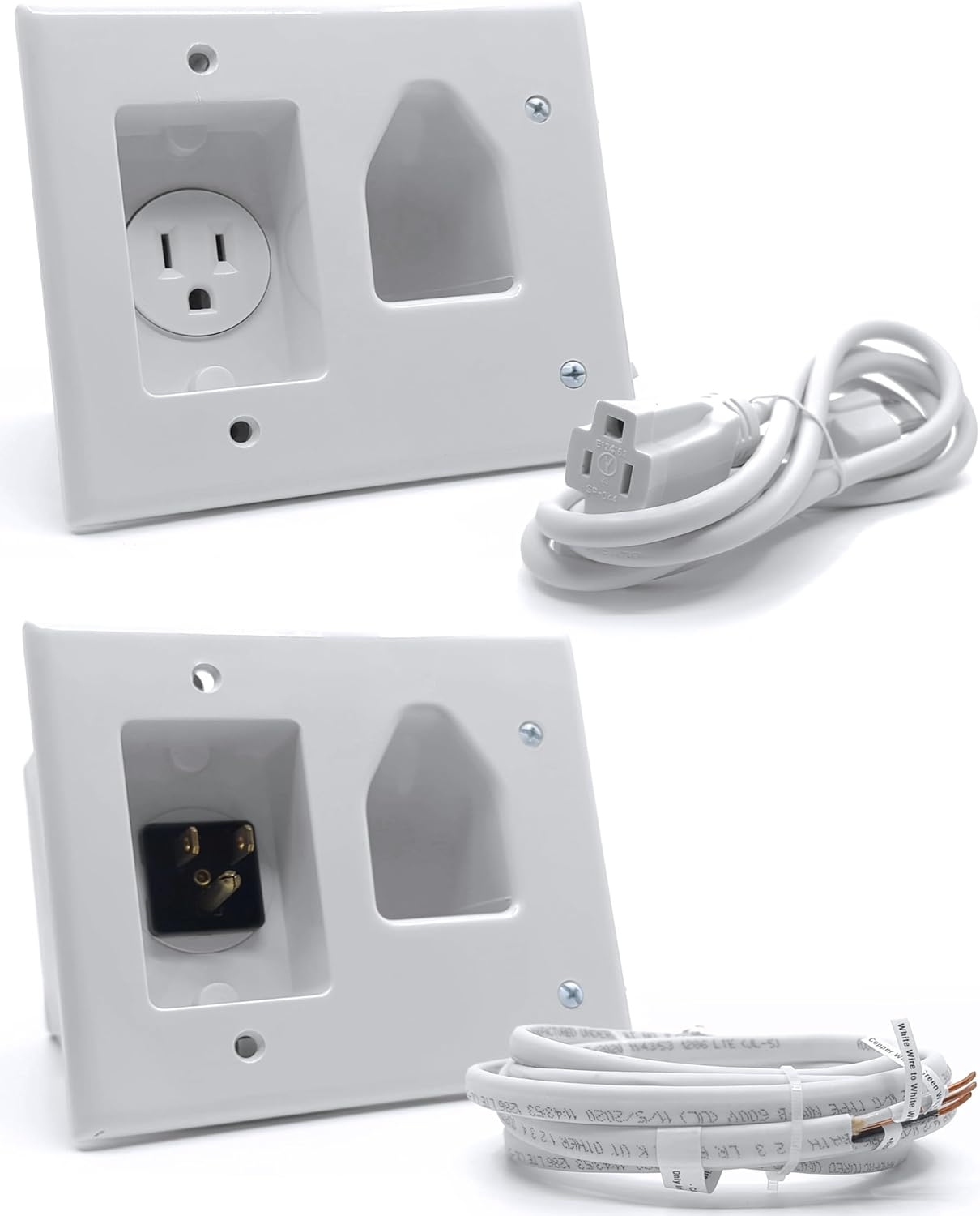
Figure 3.1: Overview of the DATA COMM In-Wall Cable Management Kit components, including the top plate with power outlet, the bottom plate with power inlet, the power extension cord, and the electrical wire.
4. Installation Guide
The DATA COMM In-Wall Cable Management Kit is designed for easy DIY installation, typically completed within 30 minutes, without the need for a professional electrician. This kit allows you to safely route both power and low-voltage cables behind your wall.
4.1. Planning and Preparation
- Determine Plate Locations: Identify the ideal placement for the top plate (behind your wall-mounted TV) and the bottom plate (near an existing power outlet). Ensure both locations are within the same wall cavity and free from obstructions like studs, pipes, or fire blocks. Use a stud finder to locate studs.
- Measure Cable Lengths: Before cutting, measure the required lengths for all cables (HDMI, Ethernet, etc.) that will be routed through the wall. Add extra length for flexibility and future adjustments.
- Test Cables: It is recommended to test all cables before routing them through the wall to ensure they are fully functional.

Figure 4.1: Illustrates the recommended placement of the top recessed plate behind the TV and the bottom recessed plate near a power outlet for optimal cable concealment.
4.2. Cutting Wall Openings
- Use Template: The kit includes a template to guide your cuts. Position the template at the desired top plate location, ensuring it is level. Trace the outline with a pencil. Repeat for the bottom plate.
- Cut Holes: Carefully cut out the traced sections using a drywall saw. For cleaner cuts, an oscillating multi-tool can be used.

Figure 4.2: Highlights the included template for precise cutting and the benefit of eliminating messy cables for a contemporary look.
4.3. Routing Cables
- Fish Electrical Wire: Feed the electrical building wire down the wall cavity from the top opening to the bottom opening. A fish tape or glow rod may be helpful for this step.
- Connect Electrical Wire: At both the top and bottom plates, strip the ends of the electrical wire and connect them to the designated terminals on the respective plates. Use the included wire nuts for secure connections.
- Route Low-Voltage Cables: Feed your HDMI, Ethernet, and other low-voltage cables through the wide recessed grooves of both the top and bottom plates. The wide opening is designed to accommodate multiple cables.

Figure 4.3: Demonstrates how multiple HDMI and Ethernet cables can be easily routed through the wide recessed grooves of both the top and bottom plates.
4.4. Securing Plates
- Insert Plates: Carefully insert the top and bottom plates into their respective wall openings.
- Tighten Mounting Wings: The plates feature metal mounting wings. Tighten the screws on these wings until they fasten securely against the back of the drywall, ensuring a flush and stable installation.

Figure 4.4: Detail of the metal mounting wings that provide a secure and flush finish by fastening tightly against the back of the wall.
4.5. Final Connections
- Connect Power Cord: Plug the female end of the included 6 ft extension cord into the straight blade inlet on the bottom recessed plate. Plug the male end into your existing wall power outlet.
- Connect TV Power: Plug your TV's power cord into the power receptacle on the top recessed plate.
- Connect AV Equipment: Connect your AV equipment (e.g., cable box, gaming console) to the low-voltage cables routed through the bottom plate.

Figure 4.5: The installed cable management kit effectively hides all cables, contributing to a cleaner and more organized home theater setup.

Figure 4.6: A visual comparison demonstrating the significant improvement in aesthetics by concealing cables with the DATA COMM kit.
5. Operation
Once installed, the DATA COMM In-Wall Cable Management Kit operates passively. It provides a safe and concealed pathway for both electrical power and low-voltage audio/video cables. Simply plug your devices into the appropriate receptacles and ports, and the system will manage the cables behind the wall, keeping your viewing area tidy.
6. Maintenance
The DATA COMM In-Wall Cable Management Kit requires minimal maintenance. Periodically inspect the visible plates for dust accumulation and clean with a soft, dry cloth. Do not use abrasive cleaners or solvents. Ensure all cable connections remain secure. No internal maintenance is required.
7. Troubleshooting
7.1. No Power to TV
- Check Connections: Ensure the 6 ft extension cord is securely plugged into both the bottom recessed plate and the wall outlet. Verify the TV's power cord is firmly plugged into the top recessed plate.
- Test Wall Outlet: Plug another device into the wall outlet to confirm it is receiving power.
- Inspect Wiring: If comfortable and safe to do so (with power off), re-check the electrical wire connections at both plates to ensure they are secure.
7.2. Cables Not Fitting Through Opening
- Verify Cable Type: The wide recessed grooves are designed for standard HDMI, Ethernet, and AV cables. Ensure you are not attempting to route excessively thick or rigid cables.
- Adjust Cable Orientation: Try re-orienting the cables as you feed them through the opening.
7.3. Plates Not Flush with Wall
- Tighten Mounting Wings: Ensure the screws for the metal mounting wings are fully tightened. These wings expand to grip the drywall securely.
- Check Wall Cut: Verify that the wall opening was cut precisely according to the template and is free of debris that might obstruct the plate.
8. Specifications
| Feature | Detail |
|---|---|
| Product Dimensions | 4.51 x 5.26 x 2.48 inches |
| Item Weight | 2 pounds |
| Model Number | 50-3323-WH-KIT |
| Brand | DATA COMM |
| Color | White |
| Material | Plastic |
| Installation Type | Screw-In |

Figure 8.1: Detailed dimensions of the top recessed plate for planning installation.
9. Warranty and Support
9.1. Return Policy
This product is subject to a 30-day return/replacement policy from the date of purchase. Please refer to your retailer's specific return guidelines for details.
9.2. Customer Support
For further assistance, technical support, or inquiries regarding your DATA COMM In-Wall Cable Management Kit, please visit the official DATA COMM Electronics website or refer to the detailed installation manual available for download. You can also contact their customer service directly through the contact information provided on their official channels.
An official installation manual in PDF format is available for download: Installation Manual (PDF)


