1. Introduction
The Sinometer DT266 is a professional digital clamp meter designed for accurate measurement of AC Current, AC Voltage, DC Voltage, Resistance, Capacitance, Frequency, and Temperature. This meter is suitable for various industrial and commercial applications, especially where non-linear loads may distort current or voltage waveforms. It features a CAT III 600V safety rating, ensuring reliable and safe operation.
2. Safety Information
Warning: This device is intended for use by certified technicians only. All safety regulations and precautions must be observed when testing high-power circuits.
- Always inspect the meter, test leads, and accessories for any damage before use. Do not use if damaged.
- Ensure the function switch is set to the correct range before making measurements.
- Do not exceed the maximum input values for any range.
- Avoid touching exposed wiring or circuit components while power is applied.
- Use caution when working with voltages above 60V DC or 30V AC RMS, as they pose a shock hazard.
- Replace the battery immediately when the low battery indicator appears to ensure accurate readings.
- Adhere to local and national safety codes.
3. Product Features
- 1000A AC Current measurement capability.
- 4-digit display count for precise readings.
- Electronic overload protection for enhanced durability.
- Continuity buzzer and Diode check functions.
- Data Hold function to freeze displayed readings.
- ACA Zero function for accurate AC current measurements.
- Peak Hold Function to capture transient peaks.
- Double molded housing for improved grip and protection.
- LCD with fast 40 segments bargraph for analog-style indication.
- Low battery indication.
- Auto Power Off feature to conserve battery life.
- CAT III 600V safety rating.
- Large jaw opening for easy clamping on large conductors.
4. Package Contents
Verify that all items are present and undamaged:
- Sinometer DT266 Digital Clamp Meter
- Test Leads (one red, one black)
- Heavy Duty Carrying Case
- Temperature Probe
- 9V Battery (may be pre-installed or included separately)

Image 1: The Sinometer DT266 Digital Clamp Meter shown with its included test leads, carrying case, and a 9V battery.
5. Setup
5.1 Battery Installation
- Ensure the meter is turned OFF.
- Locate the battery compartment cover on the back of the meter.
- Use a screwdriver to remove the screw securing the cover.
- Carefully remove the cover.
- Connect a 9V battery to the battery clips, observing correct polarity.
- Place the battery into the compartment and replace the cover, securing it with the screw.
5.2 Connecting Test Leads
For voltage, resistance, capacitance, frequency, diode, and continuity measurements:
- Insert the red test lead into the 'VΩHz' input jack.
- Insert the black test lead into the 'COM' input jack.
For temperature measurements, connect the temperature probe to the designated jacks as per the probe's instructions.
6. Operating Instructions
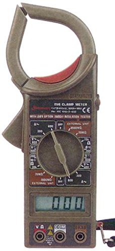
Image 2: Front view of the Sinometer DT266 Digital Clamp Meter, highlighting the display, rotary function switch, and input terminals.
6.1 Power On/Off
Rotate the central function switch from the 'OFF' position to any desired measurement function to power on the meter. To power off, rotate the switch back to 'OFF'. The meter also features an Auto Power Off function to conserve battery life after a period of inactivity.
6.2 AC Current Measurement (Clamp Function)
- Set the function switch to the desired 'A~' (AC Current) range (e.g., 200A, 1000A).
- Press the trigger to open the clamp jaws.
- Encircle only one conductor (live or neutral) with the clamp jaws. Do not clamp around multiple conductors, as this will result in an inaccurate reading of zero.
- Release the trigger to close the jaws securely around the conductor.
- Read the AC current value on the LCD display.
- Use the 'ACA Zero' button to zero out any residual readings before measurement, if available on your model.
6.3 AC/DC Voltage Measurement
- Connect the test leads as described in Section 5.2.
- Set the function switch to the desired 'V~' (AC Voltage) or 'V=' (DC Voltage) range (e.g., 200V, 600V).
- Connect the test probes in parallel across the circuit or component to be measured.
- Read the voltage value on the LCD display.
6.4 Resistance Measurement
- Connect the test leads as described in Section 5.2.
- Set the function switch to the 'Ω' (Resistance) range.
- Ensure the circuit or component to be measured is de-energized.
- Connect the test probes across the component.
- Read the resistance value on the LCD display.
6.5 Capacitance Measurement
- Connect the test leads as described in Section 5.2.
- Set the function switch to the 'F' (Capacitance) range.
- Ensure the capacitor is fully discharged before measurement.
- Connect the test probes across the capacitor terminals.
- Read the capacitance value on the LCD display.
6.6 Frequency Measurement
- Connect the test leads as described in Section 5.2.
- Set the function switch to the 'Hz' (Frequency) range.
- Connect the test probes in parallel across the signal source.
- Read the frequency value on the LCD display.
6.7 Temperature Measurement
- Connect the temperature probe to the meter's input jacks as specified by the probe manufacturer.
- Set the function switch to the '°C/°F' (Temperature) range.
- Place the tip of the temperature probe on or near the object whose temperature is to be measured.
- Read the temperature value on the LCD display.
6.8 Diode Check and Continuity
- Connect the test leads as described in Section 5.2.
- Set the function switch to the 'Diode/Continuity' symbol.
- For Diode Check: Connect the red probe to the anode and the black probe to the cathode of the diode. The display will show the forward voltage drop. Reverse the probes; the display should show 'OL' (Open Loop) for a good diode.
- For Continuity: Connect the probes across the circuit or component. If continuity exists (resistance below a certain threshold), the buzzer will sound.
6.9 Data Hold Function
Press the 'HOLD' button to freeze the current reading on the display. Press it again to release the hold and resume live readings.
7. Maintenance
7.1 Cleaning
Wipe the meter's casing with a damp cloth and mild detergent. Do not use abrasives or solvents. Ensure the meter is completely dry before use.
7.2 Battery Replacement
When the low battery indicator appears on the display, replace the 9V battery as described in Section 5.1. Dispose of old batteries responsibly.
7.3 Storage
If the meter is not used for an extended period, remove the battery to prevent leakage. Store the meter in its carrying case in a cool, dry place, away from direct sunlight and extreme temperatures.
8. Troubleshooting
- Meter does not power on: Check battery installation and ensure the battery is not depleted.
- No reading or 'OL' displayed: Ensure test leads are properly connected, the function switch is on the correct range, and the circuit is complete. For clamp measurements, ensure only one conductor is within the jaws.
- Inaccurate readings: Check battery level, ensure proper range selection, and verify test lead connections. Environmental factors like strong electromagnetic fields can also affect accuracy.
- Buzzer not sounding for continuity: The resistance may be too high, or the function switch is not set to continuity mode.
9. Specifications
| Function | Range |
|---|---|
| AC Current | 1000A |
| AC Voltage | 600V |
| DC Voltage | 600V |
| Resistance | 40MΩ |
| Capacitance | 40mF |
| Frequency | 4KHz |
| Temperature | 1000°C / 1832°F |
| Safety Rating | CAT III 600V |
| Power Source | 9V Battery |
| Dimensions (HxWxD) | 229mm x 80mm x 49mm |
| Weight | Approximately 303g (1 Pound) |
| Certification | CE |
10. Warranty and Support
The Sinometer DT266 Digital Clamp Meter typically comes with a 1-year USA warranty. For warranty claims, technical support, or service inquiries, please contact your original point of purchase or the manufacturer directly. Keep your purchase receipt as proof of purchase.


