
1. Introduction
This manual provides essential instructions for the safe and effective operation, maintenance, and troubleshooting of the Sinometer M9805G 8-Function 16-Range AC Clamp Meter. Please read this manual thoroughly before using the device.
The Sinometer M9805G is a versatile AC clamp meter designed for measuring AC/DC voltage, AC current up to 1000A, resistance, continuity, diode, and temperature in both Celsius and Fahrenheit. It features a 1999 count display, data hold function, and a back-lit LCD screen for improved readability.
Safety Information
- Always disconnect measuring terminals before removing the battery cover.
- Adhere to all local and national safety codes.
- Do not use the meter if it appears damaged or is not operating properly.
- Ensure the function switch is in the correct position for the measurement being performed.
- Observe all warnings and cautions marked on the meter.

Figure 1: Back view of the Sinometer M9805G clamp meter, highlighting safety warnings and battery compartment details. This view shows the "WARNING: TO AVOID ELECTRIC SHOCK, DISCONNECT MEASURING TERMINALS BEFORE REMOVING BATTERY COVER" label, along with compliance markings like CE and IEC1010-1.
2. Product Overview
The Sinometer M9805G is an 8-function, 16-range AC clamp meter. Key components include the clamp jaws, function selector dial, LCD display, input jacks, and control buttons.

Figure 2: Front view of the Sinometer M9805G AC Clamp Meter. This image displays the main components: the red clamp jaws, the central rotary function switch, the LCD screen, and the input terminals at the bottom. The 'HOLD' and 'LIGHT' buttons are also visible.
Package Contents
Verify that all items are present in the package:
- Sinometer M9805G Clamp Meter: 1 unit
- Test leads: 1 pair (red and black)
- K-type thermoprobe: 1 unit
- User manual: 1 copy
- 9V battery: 1 unit
- ABS Plastic carrying case: 1 unit

Figure 3: The Sinometer M9805G clamp meter, test leads, K-type thermoprobe, 9V battery, and user manual neatly arranged within its protective ABS plastic carrying case. This illustrates the complete set of items included with the product.
3. Setup
Battery Installation
- Ensure the meter is turned OFF and all test leads are disconnected.
- Locate the battery compartment cover on the back of the meter.
- Unscrew the retaining screw(s) and carefully remove the cover.
- Insert the 9V battery, observing the correct polarity (+ and -).
- Replace the battery compartment cover and secure it with the screw(s).
Initial Checks
- Before each use, inspect the meter and test leads for any signs of damage.
- Ensure the battery is properly installed and has sufficient charge.
4. Operating Instructions
The Sinometer M9805G offers multiple measurement functions. Always select the appropriate function and range before making a measurement.

Figure 4: Angled view of the Sinometer M9805G clamp meter with its LCD display active, showing "000". This image highlights the clarity of the digital display and the ergonomic design of the device during operation.
Function Selector Dial
Rotate the central dial to select the desired measurement function (e.g., AC A, DC V, AC V, Ω, °C, °F, Diode, Continuity, Hz).
AC Current Measurement (Clamp Function)
- Set the function dial to the "A" (AC Current) range.
- Press the trigger to open the clamp jaws.
- Enclose only one conductor of the circuit within the clamp jaws.
- Release the trigger to close the jaws securely around the conductor.
- Read the AC current value on the LCD display.
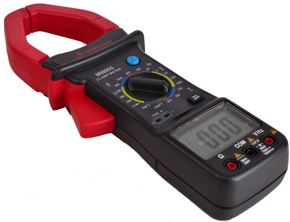
Figure 5: Angled view of the Sinometer M9805G clamp meter with its LCD display off. This perspective showcases the robust construction and the clear markings on the function selector dial, indicating various measurement ranges and functions.
Voltage Measurement (AC/DC)
- Insert the red test lead into the "VHz" input jack and the black test lead into the "COM" input jack.
- Set the function dial to the desired "V" (Voltage) range (AC or DC).
- Connect the test leads in parallel to the circuit or component under test.
- Read the voltage value on the LCD display.
Resistance Measurement
- Insert the red test lead into the "Ω" input jack and the black test lead into the "COM" input jack.
- Set the function dial to the "Ω" (Resistance) range.
- Ensure the circuit or component is de-energized.
- Connect the test leads across the component.
- Read the resistance value on the LCD display.
Temperature Measurement
- Insert the K-type thermoprobe into the "TYPE K" input jacks, observing polarity.
- Set the function dial to the "°C" or "°F" range.
- Place the thermoprobe tip on or near the object whose temperature is to be measured.
- Read the temperature value on the LCD display.
Continuity Test
- Insert the red test lead into the "Ω" input jack and the black test lead into the "COM" input jack.
- Set the function dial to the continuity symbol (usually a speaker icon).
- Ensure the circuit or component is de-energized.
- Connect the test leads across the component.
- A continuous beep indicates continuity (resistance less than 30 ohms).
Diode Test
- Insert the red test lead into the "Ω" input jack and the black test lead into the "COM" input jack.
- Set the function dial to the diode symbol.
- Ensure the diode is de-energized.
- Connect the red test lead to the anode and the black test lead to the cathode of the diode.
- Read the forward voltage drop on the display. Reverse the leads; the display should show "OL" (Open Loop) for a good diode.
Data Hold Function
Press the HOLD button to freeze the current reading on the display. Press it again to release the hold and resume live readings.
Backlight Function
Press the LIGHT button to turn on the display backlight for better visibility in low-light conditions. Press it again to turn off the backlight.
5. Maintenance
Cleaning
- Wipe the meter with a damp cloth and mild detergent. Do not use abrasives or solvents.
- Ensure the meter is completely dry before storage or next use.
Battery Replacement
When the battery low indicator appears on the display, replace the 9V battery as described in the "Battery Installation" section (Section 3).
Storage
If the meter is not used for an extended period, remove the battery to prevent leakage and store the meter in its carrying case in a cool, dry place.
6. Troubleshooting
| Problem | Possible Cause | Solution |
|---|---|---|
| No display or faint display | Low battery or incorrect battery installation | Replace battery or check polarity. |
| Incorrect readings | Incorrect function/range selected, damaged test leads, or external interference | Verify function/range. Check test leads for damage. Move away from strong electromagnetic fields. |
| "OL" (Overload) displayed | Measurement exceeds selected range or meter's maximum capacity | Select a higher range or ensure measurement is within meter's specifications. |
| No continuity beep | Resistance is too high or circuit is open | Check the circuit for breaks. Ensure resistance is below 30 ohms. |
7. Specifications
| Parameter | Value |
|---|---|
| Display | 1999 Counts |
| DC Voltage | 2/20/200V (±0.5%), 1000V (±1.0%) |
| AC Voltage | 200/750V (±1.0%) |
| AC Current | 200A (±2.0%), 1000A (±2.0% if <600A, ±3.0% if >600A) |
| Resistance | 200Ω (±1.0%), 2KΩ/2MΩ (±1.5%) |
| Temperature (°C) | 0-750°C (±1.0% if <400°C, ±2.0% if >400°C) |
| Temperature (°F) | 0-1400°F (±1.0% if <752°F, ±2.0% if >752°F) |
| Continuity Test | Less than 30 ohms |
| Diode Test | Yes |
| Max. Conductor Diameter | 55 mm |
| Power | 9V x 1 battery |
| Dimensions (L x W x H) | 282 x 104 x 47 mm (11.1 x 4.1 x 1.85 inches) |
| Weight | Approx. 500g (including battery) |
8. Warranty and Support
The Sinometer M9805G comes with a 1 Year Warranty covering parts and labor. For warranty claims or technical support, please contact your authorized Sinometer dealer or customer service.
For further assistance, refer to the official Sinometer website or contact their support channels.