1. Introduction
This manual provides essential information for the safe and efficient installation, operation, and maintenance of your Liberty Pumps Model 287 submersible sump pump. Please read all instructions carefully before installation and use. Retain this manual for future reference.
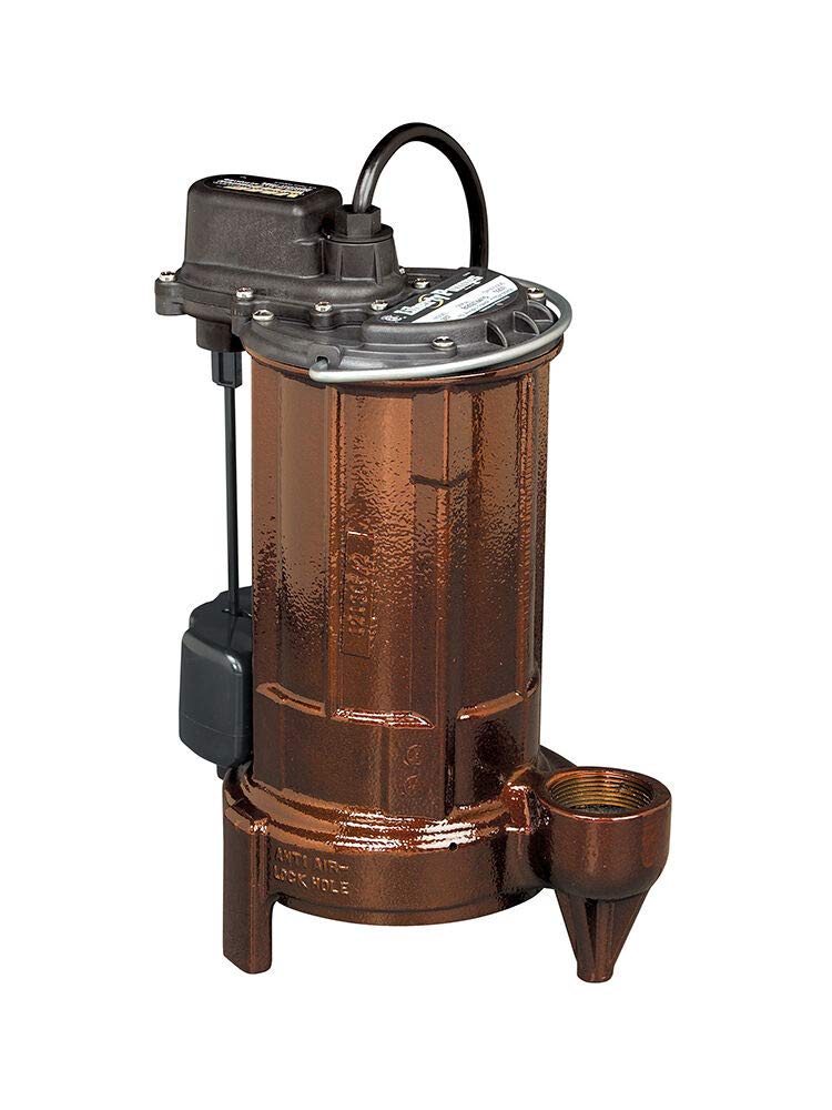
The Liberty Pumps 280-Series, including Model 287, is designed for reliable groundwater and wastewater removal in residential and commercial applications. It features a 1/2-horsepower motor, 1-1/2-inch discharge, and 3/4-inch solids-handling capability, making it suitable for various low-head to mid-range pump applications, including STEP systems, mound systems, liquid waste transfer, and high-output sump applications.
2. Safety Information
WARNING: Risk of electric shock. This pump is supplied with a grounding conductor and grounding-type attachment plug. To reduce the risk of electric shock, be certain that it is connected only to a properly grounded grounding-type receptacle.
- Always disconnect power before servicing the pump or switch.
- Do not operate the pump in an explosive atmosphere.
- Ensure the electrical supply matches the pump's voltage requirements (115 Volts).
- Do not use the pump for pumping flammable liquids.
- Keep hands clear of the pump inlet and discharge openings during operation.
- This product may expose you to chemicals including lead, which is known to the State of California to cause cancer and birth defects or other reproductive harm. For more information, go to www.P65Warnings.ca.gov.
3. Installation
3.1 Sump Pit Requirements
The Model 287 sump pump requires a sump pit no less than 10 inches in diameter to ensure proper operation and float switch movement. The pit should be clean and free of debris before pump placement.
3.2 Placement
Place the pump on a solid, level surface at the bottom of the sump pit. Ensure the pump is stable and cannot tip over during operation. Avoid placing the pump directly on dirt or gravel, as this can lead to clogging.
3.3 Discharge Piping
Connect a 1-1/2-inch discharge pipe to the pump's outlet. Use appropriate fittings and sealants to ensure a watertight connection. It is recommended to install a check valve in the discharge line to prevent water from flowing back into the sump pit when the pump shuts off. The discharge pipe should be routed to an appropriate drainage area, away from the foundation of the building.
3.4 Electrical Connection
Connect the pump's quick-connect power cord to a dedicated, properly grounded 115-volt electrical outlet. Do not use extension cords. Ensure the outlet is protected by a Ground Fault Circuit Interrupter (GFCI) for added safety.
4. Operation
The Liberty Pumps Model 287 is an automatic submersible sump pump equipped with a VMF (Vertical Magnetic Float) switch. The pump will automatically turn on when the water level in the sump pit rises to activate the float switch and turn off when the water level drops below the switch's deactivation point.
4.1 Initial Start-Up
- After installation, ensure all connections are secure and the pump is properly positioned.
- Plug the pump into the grounded GFCI outlet.
- Fill the sump pit with water to a level that activates the float switch. The pump should start and begin discharging water.
- Observe the pump's operation to ensure water is being discharged correctly and the pump cycles off once the water level drops.
4.2 Automatic Operation
Once installed and tested, the pump will operate automatically as needed. Periodically check the sump pit to ensure the pump is functioning correctly and the float switch is not obstructed.
5. Maintenance
Regular maintenance ensures the longevity and reliable operation of your sump pump.
5.1 Periodic Inspection
- Monthly: Inspect the sump pit for any debris that could obstruct the float switch or pump inlet. Remove any accumulated dirt, gravel, or other foreign objects.
- Quarterly: Test the pump by manually filling the sump pit with water to ensure it cycles on and off correctly.
- Annually: Disconnect power, remove the pump from the pit, and inspect the impeller for wear or damage. Clean the pump's exterior and inlet screen.
5.2 Cleaning
The stainless steel removable bottom screen should be cleaned regularly to prevent clogging. For thorough cleaning, disconnect power, remove the pump, and rinse the screen and impeller area with clean water. The pump's design allows for handling 3/4-inch solids, but excessive debris can still impact performance.
6. Troubleshooting
If your pump is not operating as expected, refer to the following common issues and solutions:
| Problem | Possible Cause | Solution |
|---|---|---|
| Pump does not run | No power to pump; tripped GFCI; faulty float switch; clogged impeller. | Check power supply and GFCI. Inspect float switch for obstructions. Disconnect power and clear any debris from the impeller. |
| Pump runs but does not discharge water or discharges slowly | Clogged discharge pipe; clogged impeller/inlet screen; check valve installed backward or stuck; airlock in pump. | Clear discharge pipe and impeller. Verify check valve orientation and function. Disconnect power, remove pump, and shake to release airlock. |
| Pump cycles too frequently | Float switch set too low; water re-entering sump from discharge line (no check valve or faulty check valve). | Adjust float switch. Install or inspect check valve. |
| Pump runs continuously | Float switch stuck in 'on' position; faulty float switch. | Inspect float switch for obstructions. Replace faulty float switch. |
7. Specifications
| Feature | Detail |
|---|---|
| Model Number | 287 |
| Horsepower | 0.5 HP |
| Voltage | 115 Volts |
| Material | Cast Iron |
| Discharge Size | 1-1/2 Inch |
| Solids Handling | Up to 3/4 Inch |
| Maximum Flow Rate | 75 Gallons Per Minute |
| Maximum Lifting Height | 37 Feet |
| Product Dimensions | 10"L x 10"W x 13"H |
| Item Weight | 19.46 Pounds |
| Switch Type | VMF (Vertical Magnetic Float) |
7.1 Performance Curve
This graph illustrates the pump's performance, detailing the relationship between pumping head (vertical distance water is moved) and flow rate (volume of water pumped per minute). It helps determine the pump's capacity under various operating conditions.
8. Warranty
Liberty Pumps, Inc. warrants that pumps and other products of its manufacture are free from all factory defects in material and workmanship for a period of 2 years from the date of purchase. For full warranty terms and conditions, please refer to the official warranty document included with your product or visit the manufacturer's website.
9. Support
For technical assistance, replacement parts, or further information, please contact Liberty Pumps customer support:
- Website: www.libertypumps.com
- Phone: Refer to the contact section on the official website for regional support numbers.
- Address: Liberty Pumps, Inc., 7000 Apple Tree Ave, Bergen, NY 14416, USA


