Introduction
The Sinometer MY68 is a 3 3/4 digit autoranging digital multimeter designed for accurate and convenient electrical measurements. This device is suitable for technicians and hobbyists alike, offering a wide range of functions including DC/AC voltage, DC/AC current, resistance, diode, continuity, transistor (hFE), capacitance, and frequency measurements. This manual provides essential information for the safe and effective use of your MY68 multimeter.
Safety Information
- Always read and understand this manual before operating the multimeter.
- Observe all safety precautions and warnings indicated on the meter and in this manual.
- Do not apply voltage or current that exceeds the maximum specified limits for the meter.
- Ensure the test leads are in good condition, without any cracks or damaged insulation.
- Never use the meter if it appears damaged or if the battery cover is not properly closed.
- Exercise extreme caution when working with live circuits. High voltages can be dangerous.
- Always disconnect power to the circuit and discharge all high-voltage capacitors before performing resistance, continuity, diode, or capacitance measurements.
- Use the correct function and range for your measurement to avoid damage to the meter or the circuit under test.
Setup
Package Contents
Verify that your package contains the following items:
- Sinometer MY68 Digital Multimeter
- Test Leads (one red, one black)
- Instruction Manual

Image: The Sinometer MY68 Digital Multimeter shown with its retail packaging and included test leads.
Battery Installation
The MY68 multimeter requires one 9V (6F22) battery for operation. The battery is not included in the package.
- Locate the battery compartment cover on the back of the multimeter.
- Use a screwdriver to remove the screw securing the battery cover.
- Carefully remove the cover.
- Connect a 9V battery to the battery clip, observing correct polarity.
- Place the battery into the compartment.
- Replace the battery cover and secure it with the screw.
Connecting Test Leads
Proper connection of test leads is crucial for accurate and safe measurements.

Image: The Sinometer MY68 Digital Multimeter with its red and black test leads properly connected to the input jacks.
- Insert the black test lead into the 'COM' (Common) jack. This jack is always used for the negative connection.
- For most voltage, resistance, frequency, capacitance, diode, and continuity measurements, insert the red test lead into the 'VΩFCx' jack.
- For current measurements up to 500mA, insert the red test lead into the 'mA' jack.
- For high current measurements up to 10A, insert the red test lead into the 'A' jack.

Image: A close-up view of the red and black test leads, showing their insulated bodies and protective caps for the probe tips.
Always ensure test leads are fully inserted into the correct jacks before taking measurements.
Operating Instructions
Multimeter Overview
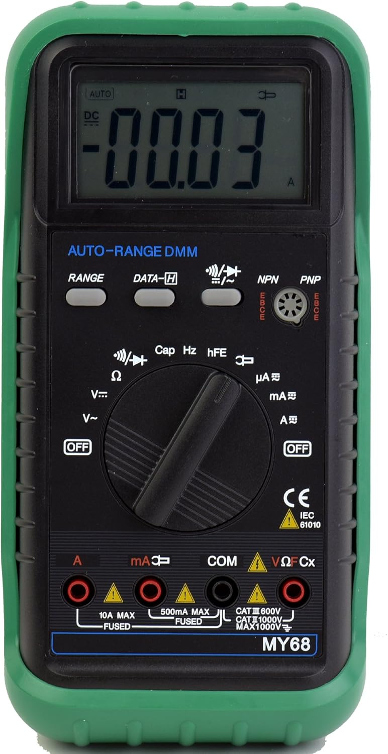
Image: A detailed front view of the Sinometer MY68 Digital Multimeter, highlighting its LCD display, central rotary function switch, and various input jacks.
The MY68 features a large LCD display, a central rotary switch for function selection, and several input jacks for test leads. It also includes buttons for 'RANGE' and 'DATA-H'.
Powering On/Off
To power on the multimeter, rotate the central function switch from the 'OFF' position to any desired measurement function. To power off, rotate the switch back to the 'OFF' position.
Function Selection
The rotary switch allows you to select the desired measurement function. The MY68 is an autoranging multimeter, meaning it automatically selects the appropriate range for most measurements. However, a 'RANGE' button is provided for manual range selection if needed.
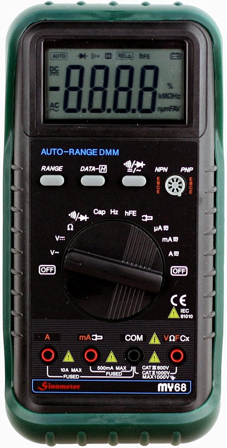
Image: A close-up of the Sinometer MY68's rotary switch, clearly showing the various measurement functions such as voltage, current, resistance, capacitance, and frequency.
Measurement Modes
- DC Voltage (V-): Rotate the switch to the 'V-' position. Connect the red lead to the positive side of the circuit and the black lead to the negative side. The display will show the DC voltage.
- AC Voltage (V~): Rotate the switch to the 'V~' position. Connect the test leads across the AC voltage source. The display will show the AC voltage.
- DC Current (A-, mA-, uA-): Rotate the switch to the appropriate current range (A-, mA-, or uA-). Ensure the red lead is in the correct current input jack (mA or A). Connect the meter in series with the circuit.
- AC Current (A~, mA~, uA~): Rotate the switch to the appropriate current range (A~, mA~, or uA~). Ensure the red lead is in the correct current input jack (mA or A). Connect the meter in series with the circuit.
- Resistance (Ω): Rotate the switch to the 'Ω' position. Ensure the circuit is de-energized. Connect the test leads across the component to measure its resistance.
- Capacitance (Cap): Rotate the switch to the 'Cap' position. Ensure the capacitor is discharged before connecting the leads. Connect the test leads across the capacitor.
- Frequency (Hz): Rotate the switch to the 'Hz' position. Connect the test leads across the signal source to measure its frequency.
- Diode Test: Rotate the switch to the diode symbol. Connect the red lead to the anode and the black lead to the cathode of the diode. The display will show the forward voltage drop. Reverse the leads to check for open circuit.
- Continuity Test: Rotate the switch to the continuity symbol. If the resistance between the two points is low (typically less than 50Ω), the built-in buzzer will sound, indicating continuity.
- Transistor (hFE) Test: Rotate the switch to the 'hFE' position. Insert the transistor leads into the appropriate NPN or PNP sockets on the meter. The display will show the hFE value.
Special Features
- Auto/Manual Range (RANGE): Press the 'RANGE' button to switch between auto-ranging and manual-ranging modes. In manual mode, press the button repeatedly to cycle through available ranges.
- Data Hold (DATA-H): Press the 'DATA-H' button to freeze the current reading on the display. Press it again to release the hold function.
- Low Battery Indication: A battery symbol will appear on the LCD when the battery voltage is low, indicating that the battery needs replacement.
- Over Range Indication: The LCD will display 'OL' (Over Load) when the input exceeds the selected range.
Maintenance
Battery Replacement
When the low battery indicator appears on the display, replace the 9V battery as described in the 'Battery Installation' section.
Fuse Replacement
The MY68 multimeter is protected by fuses. If the current measurement function stops working, the fuse may need replacement. Refer to the specifications for the correct fuse ratings (e.g., 500mA MAX FUSED and 10A MAX FUSED). Fuse replacement typically requires opening the meter's casing, which should only be performed by qualified personnel.
Cleaning
Wipe the meter with a damp cloth and a mild detergent. Do not use abrasives or solvents. Ensure the meter is completely dry before use.
Storage
If the meter is not to be used for an extended period, remove the battery to prevent leakage and store it in a cool, dry place.
Troubleshooting
- Meter does not power on: Check battery installation and ensure the battery has sufficient charge.
- 'OL' displayed: The measured value exceeds the selected range. Switch to a higher range or ensure the meter is in auto-ranging mode.
- No reading or inaccurate reading: Ensure test leads are correctly inserted into the appropriate jacks for the selected function. Check for damaged test leads. Verify the circuit is properly connected.
- Current measurement not working: Check the fuse for the current input. Replace if blown.
Specifications
| Measurement | Range | Accuracy |
|---|---|---|
| DC Voltage | 400mV/4V/40V/400V/1000V | ±(0.7%+2) to ±(0.8%+2) |
| AC Voltage | 400mV/4V/40V/400V/750V | ±(3%+3) to ±(1.0%+3) |
| DC Current | 400uA/4000uA/40mA/400mA/10A | ±(1.0%+5) to ±(1.5%+5) |
| AC Current | 400uA/4000uA/40mA/400mA/10A | ±(1.5%+5) to ±(2.0%+10) |
| Resistance | 400Ω/4kΩ/40kΩ/400kΩ/4MΩ/40MΩ | ±(1.2%+2) to ±(2%+5) |
| Capacitance | 4nF/40nF/400nF/4uF/40uF/200uF | ±(4.0%+15) |
| Frequency | 9.99/100/1000/10k/200kHz | ±2.0% |
General Characteristics
- Power Supply: 1 x 6F22 9V battery (not included)
- Dimensions: 91(W) x 189(L) x 20.5(H) mm (approximately 3.58 x 7.44 x 0.81 inches)
- Weight: Approximately 310g (including battery)
- Display: 3 3/4 digits LCD
- Over Range Indication: 'OL'
- Low Battery Indication: Battery symbol on display
Warranty and Support
Warranty information for the Sinometer MY68 Digital Multimeter is typically provided at the point of purchase or within separate documentation included with the product. For specific warranty details, claims, or technical support, please refer to the manufacturer's official website or contact their customer service department directly. Keep your purchase receipt as proof of purchase.