Introduction
This manual provides essential information for the safe and effective use of the Sperry Instruments VC61000 Volt Check Voltage & Continuity Tester. This heavy-duty, multi-function tool is designed to indicate voltage levels, test continuity, and allow non-contact AC voltage detection. It features Smart Meter Technology, automatically adjusting to the required application without manual dial adjustments. Please read this manual thoroughly before operation and retain it for future reference.
Important Safety Information
WARNING: Electrical shock hazard. Always exercise extreme caution when working with electrical circuits. Failure to follow safety precautions can result in serious injury or death.
- Always assume circuits are live until verified otherwise.
- Wear appropriate personal protective equipment (PPE), including safety glasses and insulated gloves.
- Do not use the tester if it appears damaged or if the test leads are frayed or broken.
- Ensure the tester's CAT rating (CAT IV 600V/CAT III 1000 V) is suitable for the application.
- Keep fingers behind the finger guards on the test probes during use.
- Proposition 65 Warning: This product may expose you to chemicals known to the State of California to cause cancer and birth defects or other reproductive harm. For more information, visit www.P65Warnings.ca.gov.
Product Features
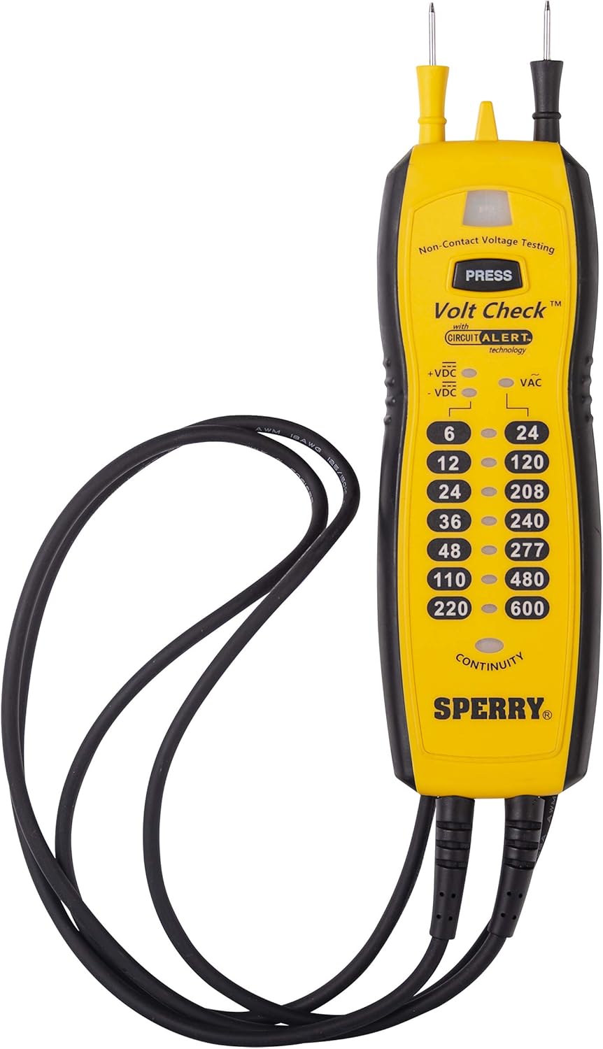
The Sperry Instruments VC61000 Volt Check Tester offers a range of features designed for reliability and ease of use:
- Voltage Indication: Indicates AC/DC voltage levels from 6V to 600V.
- Continuity Testing: Provides continuity indication.
- Non-Contact AC Voltage Detection (Circuit Alert): Integrated sensor in the tip detects AC voltage (50-600V AC) without direct contact.
- Smart Meter Technology: Automatically adjusts to the required application (voltage, continuity, or range) without manual dial adjustments.
- DC Polarity Indication: Clearly shows the polarity of DC voltage.
- Magnetic Back: Allows the tester to attach to electrical panels, freeing hands during testing.
- Durable Construction: Engineered for demanding environments with a 10-foot drop rating and 250-pound crush rating.
- Sta-Flex Cold Weather Leads: 26-inch leads designed to remain flexible in cold temperatures, with strain reliefs for durability.
- Integral Probe Storage: Probes snap into the unit for compact storage and are spaced to fit standard outlets for one-handed operation.

Package Contents
Verify that all items are present upon unpacking:
- Sperry Instruments VC61000 Volt Check Voltage & Continuity Tester
- 3 AAA Batteries (pre-installed or included separately)
Setup
Battery Installation
- Locate the battery compartment cover on the back of the tester.
- Use a screwdriver to remove the screw securing the cover.
- Insert three (3) AAA batteries, observing the correct polarity (+/-) as indicated inside the compartment.
- Replace the battery compartment cover and secure it with the screw.
Initial Check
Before each use, it is recommended to test the unit on a known live circuit to ensure proper functionality.
Operating Instructions
1. Voltage Testing (AC/DC)
The VC61000 automatically detects AC or DC voltage and displays the approximate level using LED indicators.
- Ensure the test leads are securely connected to the tester.
- Carefully touch the tips of the test probes to the circuit points you wish to measure. For outlets, the probes are spaced to fit directly into the slots.
- Observe the illuminated LEDs on the tester. The highest illuminated LED indicates the approximate voltage level.
- For DC voltage, the +/- VDC indicators will show the polarity.


2. Continuity Testing
The tester can determine if a circuit or component has a continuous electrical path.
- Ensure the circuit or component is de-energized before performing a continuity test.
- Touch the tips of the test probes to the two points you wish to test for continuity.
- If continuity is present, the "CONTINUITY" LED indicator will illuminate.
3. Non-Contact AC Voltage Detection (Circuit Alert)
This feature allows for quick detection of live AC voltage without direct contact with conductors.
- Press and hold the "PRESS" button located near the tip of the tester.
- Move the tip of the tester close to the conductor, outlet, or circuit breaker you suspect is live.
- If AC voltage is detected, the tip will illuminate, and an audible alert will sound.
- Release the "PRESS" button to turn off the non-contact detection feature.


4. Using the Magnetic Back
The integrated magnets on the back of the tester allow for hands-free operation when working near metallic surfaces like electrical panels.

Maintenance
Cleaning
Wipe the tester and leads with a damp cloth. Do not use abrasive cleaners or solvents. Ensure the unit is dry before storage or next use.
Battery Replacement
Replace batteries when the indicators become dim or the unit fails to power on. Refer to the "Battery Installation" section under Setup for instructions.
Lead Inspection
Regularly inspect the test leads for any signs of damage, such as cuts, cracks, or frayed insulation. Damaged leads must be replaced immediately to prevent electrical shock hazards.
Troubleshooting
| Problem | Possible Cause | Solution |
|---|---|---|
| Tester does not power on or indicators are dim. | Low or dead batteries. | Replace the AAA batteries. |
| Inconsistent voltage or continuity readings. | Damaged test leads or poor contact. | Inspect leads for damage; ensure firm contact with test points. Replace leads if damaged. |
| Non-contact AC voltage detection not working. | Battery low, or not holding "PRESS" button. | Replace batteries. Ensure the "PRESS" button is held down during detection. |
Specifications
| Feature | Detail |
|---|---|
| Brand | SPERRY |
| Model Number | VC61000 |
| Measurement Type | Voltage, Continuity, Non-Contact AC Voltage |
| AC Voltage Range | 24-600V AC (Twin probes), 50-600V AC (Non-contact) |
| DC Voltage Range | 6-220V DC |
| Safety Rating | CAT IV 600V / CAT III 1000V |
| Power Source | 3 x AAA Batteries (included) |
| Item Weight | 3.52 ounces (0.22 Pounds) |
| Product Dimensions (L x W x H) | 9 x 2.25 x 0.5 inches |
| Leads | 26-inch Sta-Flex cold-weather leads |
| Color | Yellow |
Warranty and Support
Warranty Information
Sperry Instruments products are designed for durability and reliability. This product is backed by a manufacturer's warranty. For specific details regarding the warranty period and coverage, please refer to the documentation included with your purchase or visit the official Sperry Instruments website.
Customer Support
Should you encounter any issues or have questions regarding the operation, maintenance, or troubleshooting of your VC61000 Volt Check Tester, please contact Sperry Instruments customer support. Contact information can typically be found on the product packaging or the official Sperry Instruments website.


