1. Introduction
The DEI Directed Electronics 506T Audio Sensor is an essential component for enhancing vehicle security systems. This sensor is specifically engineered to detect the distinct sound frequency associated with breaking glass, providing an immediate alert to your vehicle's alarm system in the event of a potential break-in or tampering. Its precise tuning minimizes false alarms while ensuring reliable detection of glass-break incidents.
2. Product Overview
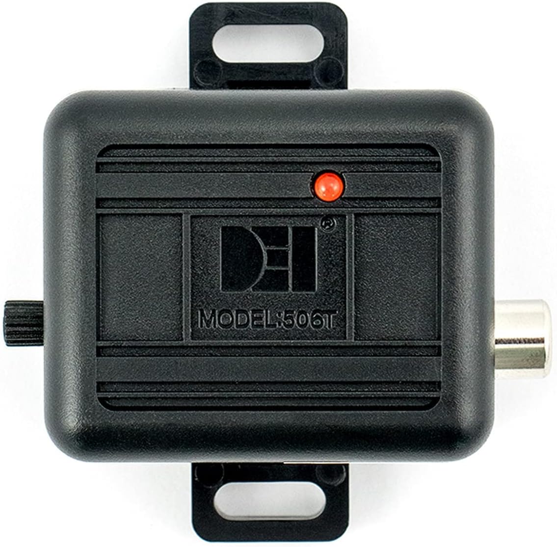
The 506T Audio Sensor consists of a main control unit, a sensitive microphone, and a wiring harness designed for integration with compatible vehicle alarm systems. Its compact design allows for discreet installation within the vehicle's interior.
Key Features:
- Glass-Break Detection: Specifically tuned to identify the acoustic signature of breaking glass.
- Adjustable Sensitivity: Allows for fine-tuning to suit various vehicle environments and minimize false triggers.
- Direct Compatibility: Designed for seamless integration with Directed Electronics alarm systems.
- Compact Design: Facilitates flexible mounting options within the vehicle.
Components:


3. Setup and Installation
Proper installation is crucial for the optimal performance of the 506T Audio Sensor. It is recommended that installation be performed by a qualified professional, especially if you are unfamiliar with vehicle electrical systems.
3.1 Mounting the Microphone
The microphone is the primary detection component. It should be mounted in a location that provides clear acoustic access to all vehicle windows. Common mounting locations include:
- On the windshield, behind the rearview mirror.
- On an A-pillar, facing the dashboard.
- On the rear glass, if rear window protection is a priority.
The microphone can be secured using the provided bracket with 3M double-sided tape or by drilling a 1/2-inch hole and pushing the microphone through for a flush mount. Ensure the microphone is not obstructed by interior trim or other objects.
3.2 Connecting the Control Unit
The 506T control unit connects to your vehicle's alarm system via the supplied wiring harness. For Directed Electronics alarm systems, this sensor is typically plug-and-play, connecting to a dedicated sensor port. You may need to acquire a longer RCA cable depending on the chosen mounting locations for the microphone and control unit.
- Connect the microphone's RCA cable to the corresponding input on the 506T control unit.
- Connect the wiring harness from the 506T control unit to the designated sensor input on your vehicle's alarm system. Refer to your alarm system's manual for specific wiring diagrams.
- Secure the 506T control unit in a hidden, accessible location, ensuring it is protected from moisture and extreme temperatures.
4. Operating Instructions
Once installed, the 506T Audio Sensor requires calibration to ensure optimal performance and prevent false alarms.
4.1 Sensitivity Adjustment
The sensor's sensitivity is adjusted via a rotary knob located on the control unit. A red LED indicator provides visual feedback during adjustment.
- Ensure all vehicle windows are closed.
- Arm your vehicle's alarm system.
- Slowly turn the sensitivity knob to increase or decrease the detection threshold.
- Test the sensor by gently tapping keys or a coin against the exterior of each window, starting with the window farthest from the microphone.
- Adjust the sensitivity until the sensor reliably triggers the alarm when tapping the farthest window, but does not trigger from normal ambient noises or light vibrations.
- The red LED will illuminate when the sensor detects a sound event that meets the set sensitivity threshold.
Finding the correct balance is key. High sensitivity may lead to false alarms from loud noises (e.g., sirens, thunder, heavy rain), while low sensitivity may fail to detect actual glass-break attempts.
5. Maintenance
The DEI 506T Audio Sensor is designed for long-term, maintenance-free operation. However, periodic checks can ensure continued reliability:
- Visual Inspection: Periodically check the microphone and control unit for any visible damage or loose connections.
- Cleanliness: Ensure the microphone is free from dust, debris, or obstructions that could impair its acoustic detection. Use a soft, dry cloth for cleaning.
- Functionality Test: Perform a sensitivity test (as described in Section 4.1) annually or after any significant vehicle modifications to confirm proper operation.
6. Troubleshooting
If you encounter issues with your 506T Audio Sensor, consider the following troubleshooting steps:
6.1 Sensor Not Triggering Alarm
- Check Sensitivity: Ensure the sensitivity knob is adjusted to an appropriate level. Increase sensitivity gradually and re-test.
- Microphone Placement: Verify the microphone is not obstructed and is positioned to adequately cover all windows.
- Wiring Connections: Inspect all wiring for secure connections. Ensure the RCA cable is fully seated and the harness is correctly connected to the alarm system.
- Alarm System Compatibility: Confirm that your alarm system is compatible with external sensors and that the input is enabled.
6.2 False Alarms
- Reduce Sensitivity: If the alarm triggers from loud external noises (e.g., sirens, heavy trucks, thunder) or vibrations, decrease the sensitivity setting.
- Microphone Mounting: Ensure the microphone is securely mounted and not vibrating against other surfaces, which could cause false triggers.
- Environmental Factors: Consider if extreme weather conditions (e.g., heavy rain, hail) are contributing to false alarms and adjust sensitivity accordingly.
If issues persist after troubleshooting, contact a professional installer or the manufacturer's support.
7. Specifications
| Specification | Detail |
|---|---|
| Brand | Design Engineering |
| Model Number | 506T |
| Product Dimensions | 5 x 5 x 5 inches |
| Item Weight | 4.8 ounces (0.3 Pounds) |
| Power Source | Battery Powered (refer to alarm system for power) |
| Maximum Range | 12 Meters (detection range) |
| Mounting Type | Internal Mounting |
| Compatible Devices | Directed Electronics alarm systems |
| Recommended Uses | Vehicle security |
8. Warranty and Support
8.1 Legal Disclaimer
Please note that the product warranty does not cover misuse of the product. Ensure the sensor is installed and operated according to the guidelines provided in this manual to maintain warranty validity.
8.2 Customer Support
For technical assistance, installation questions, or warranty claims, please contact Design Engineering customer support. Refer to the official Design Engineering website or product packaging for the most current contact information.