1. Introduction
The Honeywell L7224U-1002 is a universal electronic oil aquastat designed for oil-fired hydronic heating appliances. This device electronically monitors and controls circulator, burner, and boiler temperatures, providing precise electronic temperature sensing. It features EnviraCOM communication capability for remote monitoring when used with the Honeywell EnviraLINK service. The aquastat offers multizone control and maintains accuracy within +/-2 degrees Fahrenheit. Its LED display provides diagnostic and status information, and the low limit can be disabled for cold start boiler applications. This manual provides essential information for the safe and effective installation, operation, and maintenance of your L7224U-1002 aquastat.
2. Setup and Installation
Proper installation is crucial for the safe and efficient operation of the aquastat. Always prioritize safety and follow all local electrical codes.
2.1 Safety Precautions
- Disconnect Power: Always disconnect the main power supply to the heating system before beginning any installation, wiring, or service work.
- Qualified Personnel: Electrical work should be performed by a qualified and licensed technician.
- Local Codes: Ensure all installation procedures comply with local electrical and building codes.
2.2 Mounting Options
The L7224U-1002 aquastat offers flexible mounting options:
- Direct Mounting: Can be mounted directly to the boiler.
- Remote Mounting: Can be mounted remotely from the aquastat well.
- Flush Mounting: Can be flush-mounted to a surface.
- Orientation: Supports both vertical and horizontal orientations.
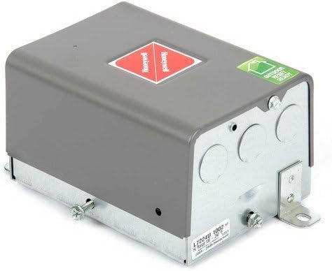
Figure 1: External view of the Honeywell L7224U-1002 Aquastat. This image shows the grey metal casing with mounting brackets and conduit knockouts, indicating its robust construction and various installation points.
2.3 Wiring
Refer to the detailed wiring diagram provided with your product packaging for specific terminal connections. The aquastat manages the circulator, burner, and boiler temperatures. Ensure all electrical connections are secure and properly insulated.

Figure 2: Internal view of the Honeywell L7224U-1002 Aquastat circuit board. This image displays the electronic components, wiring terminals, relays, and the LED display, highlighting the device's internal complexity and connection points for various system components.
2.4 Sensor Installation
The electronic temperature sensor (probe) must be correctly inserted into the boiler's aquastat well. This ensures accurate temperature readings, which are critical for the aquastat's control functions.
2.5 Replacing an Existing Aquastat
When replacing an older aquastat, it is recommended to:
- Take a photograph of the existing wiring before disconnecting any wires.
- Label each wire clearly as it is disconnected from the old unit.
- Connect wires one by one to the corresponding terminals on the new L7224U-1002 aquastat, following the wiring diagram.
3. Operating Instructions
Once installed and wired, the aquastat is ready for operation. Follow these steps to configure and monitor your heating system.
3.1 Power On
After completing all installation and wiring steps, restore power to the heating system. The aquastat will initiate its startup sequence.
3.2 LED Display and Status
The integrated LED display provides real-time information:
- Current Boiler Temperature: Displays the temperature sensed by the probe.
- System Status: Indicates operational modes (e.g., heating, idle).
- Diagnostic Codes: Shows error codes if a fault is detected.
3.3 Setting Temperatures and Differentials
The L7224U-1002 allows for precise control over boiler temperatures. Refer to the specific programming instructions included with your unit for detailed steps on adjusting these settings:
- High Limit: Sets the maximum desired boiler water temperature. The burner will shut off when this temperature is reached.
- Low Limit: Sets the minimum desired boiler water temperature. This is often used to maintain a warm boiler for domestic hot water production.
- Differential: Determines the temperature drop from the setpoint before the burner reactivates. This prevents rapid cycling of the burner.
3.4 Cold Start Boiler Applications
For systems that do not require a minimum boiler temperature (e.g., cold start boilers), the low limit function can be disabled. Consult your product documentation for instructions on how to disable this feature.
3.5 EnviraCOM Communication
If you intend to use the EnviraCOM communication feature for remote monitoring, ensure the aquastat is properly connected to the Honeywell EnviraLINK service. Refer to the EnviraLINK documentation for setup and usage details.
4. Maintenance
Regular maintenance helps ensure the longevity and optimal performance of your aquastat and heating system.
- Periodic Inspection: Annually inspect the aquastat, its wiring, and connections for any signs of wear, damage, or looseness.
- Cleaning: Keep the exterior of the aquastat clean and free from dust and debris. Use a soft, dry cloth for cleaning. Avoid using abrasive cleaners, solvents, or harsh chemicals.
- Sensor Integrity: Verify that the temperature sensor remains securely in its well and shows no signs of corrosion or physical damage.
- Professional Servicing: It is highly recommended to have your entire heating system, including the aquastat, inspected and serviced annually by a qualified HVAC technician.
5. Troubleshooting
This section provides guidance for common issues you might encounter. For complex problems or if these steps do not resolve the issue, contact a qualified technician.
| Problem | Possible Cause | Solution |
|---|---|---|
| No power to aquastat / No LED display | Main power disconnected, tripped circuit breaker, loose wiring. | Check main power supply. Reset circuit breaker. Verify all wiring connections are secure. |
| Incorrect temperature readings | Temperature sensor not fully inserted or damaged. | Ensure sensor is fully inserted into the well. Inspect sensor wire for damage. |
| Burner not firing / Circulator not running | High/low limit settings incorrect, thermostat not calling for heat, diagnostic error code. | Verify high/low limit settings. Check thermostat operation. Look for diagnostic codes on LED display. |
| LED display shows "Err 3" | Hardware fault. | This code indicates a hardware malfunction. The control unit typically requires replacement. |
| Other diagnostic codes | Specific system fault. | Refer to the complete product manual for a list of diagnostic codes and their corresponding solutions. |
If troubleshooting steps do not resolve the problem, contact a qualified HVAC technician or Honeywell customer support for further assistance.
6. Specifications
Technical specifications for the Honeywell L7224U-1002 Universal Electronic Oil Aquastat:
- Model: L7224U-1002
- Voltage: 120V
- Frequency: 60 Hz
- Power Consumption: 7 VA
- Operating Temperature (High Limit): 130 to 240 degrees F (54 to 116 degrees C)
- Operating Temperature (Low Limit): 110 to 220 degrees F (43 to 104 degrees C)
- Differential Temperature (High Limit): 5 to 20 degrees F (adjustable)
- Differential Temperature (Low Limit): 10 to 25 degrees F (adjustable)
- Electrical Ratings (Burner): 7.4A at 120V (full load); 44.4 A inrush (locked rotor)
- Electrical Ratings (Circulator): 7.4A at 120V (full load); 44.4 A inrush (locked rotor)
- Ambient Temperature Range: -30 to +150 degrees F (-34 to +66 degrees C)
- Dimensions (L x W x H): 4-1/4 x 2-5/8 x 7-1/8 inches (109 x 67 x 181 mm)
- Material: Copper (sensor), other components as per design.
- Certifications: UL recognized.
- Communication: EnviraCOM enabled.
7. Warranty and Support
For detailed warranty information, terms, and conditions, please refer to the documentation included with your Honeywell L7224U-1002 aquastat. For technical assistance, product support, or to inquire about warranty claims, please visit the official Honeywell website or contact Honeywell customer service directly. Ensure you have your product model number and purchase details available when seeking support.