
1. Introduction
This manual provides detailed instructions for the installation, operation, and maintenance of your White-Rodgers LASCO 36-0181 Universal Heat and Cool Thermostat. This thermostat is designed for most 24-volt heating and cooling applications. Please read this manual thoroughly before beginning installation or operation to ensure proper function and safety.
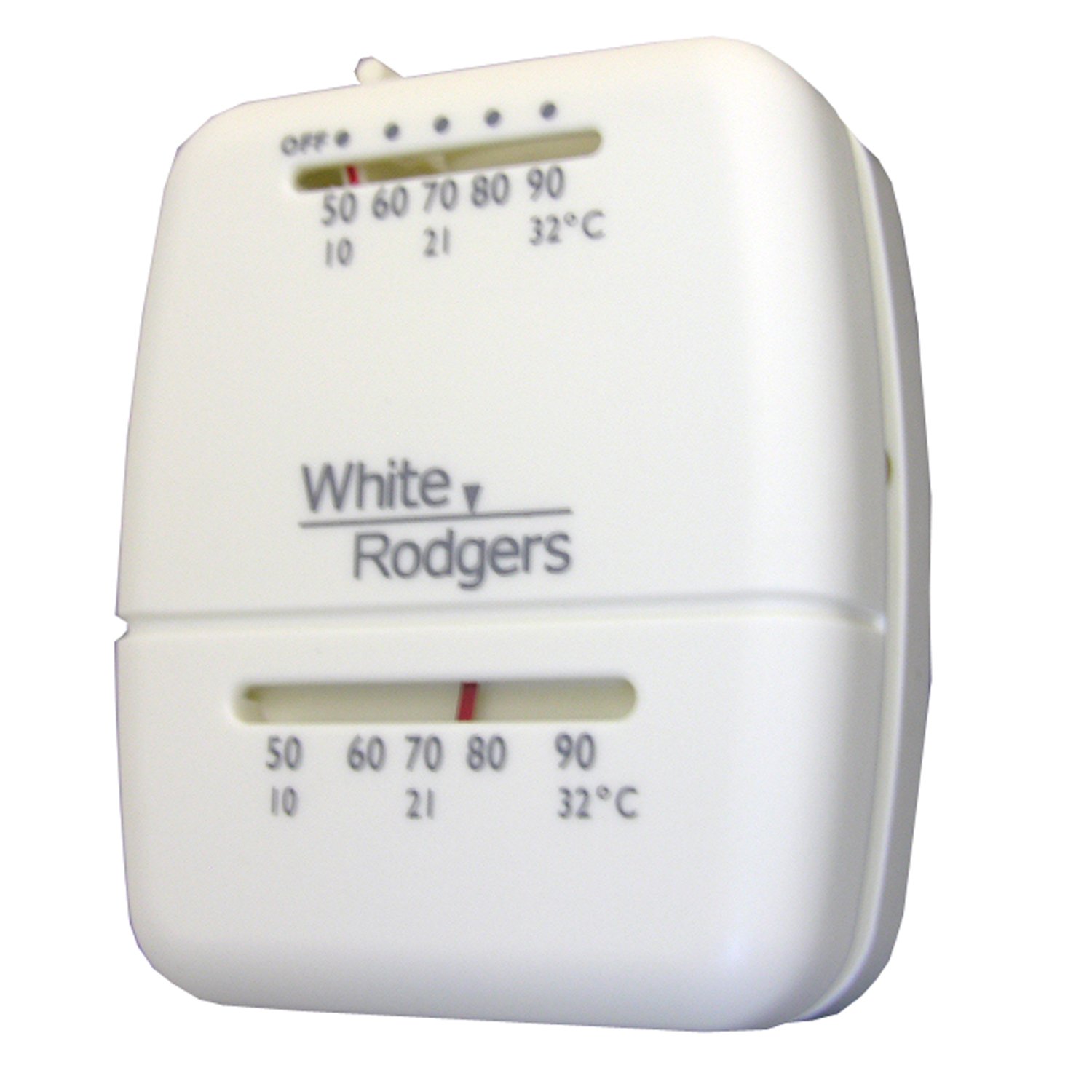
Figure 1: Front view of the White-Rodgers LASCO 36-0181 Universal Heat and Cool Thermostat. This image displays the thermostat's white plastic casing and manual controls.
2. Safety Information
- WARNING: Always turn off power to the heating/cooling system at the main circuit breaker or fuse box before installing or servicing the thermostat. Failure to do so can result in electrical shock or equipment damage.
- This thermostat is designed for 24-volt systems only. Do not use it with line voltage systems (120V or 240V).
- Ensure all wiring connections are secure and comply with local electrical codes.
- If you are unsure about any part of the installation process, consult a qualified HVAC technician or electrician.
- Keep this manual for future reference.
3. Package Contents
Verify that your package contains the following items:
- White-Rodgers LASCO 36-0181 Universal Heat and Cool Thermostat
- Mounting Hardware (screws, wall anchors)
- User Manual (this document)
4. Installation and Setup
4.1. Tools Required
- Screwdriver (Phillips head)
- Drill with appropriate drill bit (if new mounting holes are needed)
- Wire strippers (if wires need to be prepared)
4.2. Removing the Old Thermostat
- Turn off power: Locate the circuit breaker or fuse box that controls your heating and cooling system and turn off the power.
- Remove cover: Carefully remove the cover of your old thermostat.
- Photograph wiring: Take a picture of the existing wiring connections. This will be a helpful reference.
- Label wires: Label each wire with the terminal designation it was connected to (e.g., R, W, Y, G, C).
- Disconnect wires: Disconnect the wires from the old thermostat terminals.
- Remove old base: Unscrew and remove the old thermostat's mounting base from the wall.
4.3. Mounting the New Thermostat
- Separate base: Gently separate the front cover of the new thermostat from its mounting base.
- Position base: Hold the new thermostat's mounting base against the wall where you want to install it. Use the existing mounting holes if possible, or mark new ones.
- Secure base: Drill pilot holes if necessary and secure the mounting base to the wall using the provided screws and wall anchors. Ensure the base is level.
5. Wiring Diagram
The LASCO 36-0181 thermostat is designed for standard 24-volt heating and cooling systems. Refer to the wiring diagram below and your system's specific wiring instructions. If your old thermostat had different terminal designations, consult a professional.
| Thermostat Terminal | Typical Wire Function |
|---|---|
| R | 24V Hot (Power) |
| W | Heat Call |
| Y | Cool Call |
| G | Fan Call |
| C | 24V Common (Optional, for continuous power if applicable) |
Wiring Steps:
- Match the labeled wires from your old thermostat to the corresponding terminals on the new LASCO 36-0181 thermostat's mounting base.
- Insert each wire into its designated terminal and tighten the screw securely. Ensure no bare wire is exposed outside the terminal.
- Once all wires are connected, carefully push any excess wire back into the wall opening.
- Attach the thermostat front cover to the mounting base, ensuring it snaps securely into place.
- Restore power: Turn the power back on at the main circuit breaker or fuse box.
6. Operating Instructions
The LASCO 36-0181 thermostat features simple, manual controls for ease of use.
6.1. System Switch (OFF/ON)
This switch controls the overall power to the heating and cooling system through the thermostat.
- OFF: Turns off the heating and cooling system. The thermostat will not activate the system.
- ON: Enables the thermostat to control the heating or cooling system based on the temperature setting and mode selection.
6.2. Mode Selector (HEAT/COOL)
This switch selects the operating mode for your HVAC system.
- HEAT: The thermostat will activate the heating system when the room temperature falls below your setpoint.
- COOL: The thermostat will activate the cooling system when the room temperature rises above your setpoint.
6.3. Temperature Adjustment
Adjust the temperature setpoint by moving the slider or rotating the dial (depending on the specific model's design) to your desired temperature. The bi-metal thermometer will display the current room temperature.
6.4. Heat Anticipator Adjustment
The adjustable heat anticipator helps to prevent temperature overshoot and provides more consistent heating. This is typically a small lever or screw located inside the thermostat cover. Adjust it according to your heating system's current draw (usually found on the furnace's control board or in its manual). A common starting point is to set it to match the current draw of your heating system's control circuit. Adjusting it slightly higher will cause shorter heating cycles, while adjusting it lower will result in longer cycles.
7. Maintenance
- Cleaning: Periodically wipe the exterior of the thermostat with a soft, damp cloth. Do not use abrasive cleaners or solvents. Ensure no moisture enters the internal components.
- Airflow: Ensure that the thermostat's vents (if any) are not blocked by dust or debris, as this can affect temperature readings.
- Annual Check: It is recommended to have your HVAC system and thermostat checked annually by a qualified technician to ensure optimal performance.
8. Troubleshooting
If you experience issues with your thermostat, try the following steps before contacting support:
- No Power to Thermostat/System:
- Check the circuit breaker or fuse for your heating/cooling system. Reset if tripped.
- Ensure the system switch on the thermostat is set to "ON".
- System Not Heating/Cooling:
- Verify the mode selector is set to "HEAT" or "COOL" as desired.
- Adjust the temperature setpoint to be significantly higher (for heat) or lower (for cool) than the current room temperature to trigger the system.
- Check that the furnace or air handler's power switch is on.
- Inspect wiring connections at the thermostat and the HVAC unit for looseness or corrosion.
- Inaccurate Temperature Reading:
- Ensure the thermostat is not exposed to direct sunlight, drafts, or heat sources (e.g., lamps, appliances) that could affect its sensor.
- Clean any dust or debris from the thermostat's vents.
- System Cycles Too Frequently/Infrequently:
- Adjust the heat anticipator setting (see Section 6.4).
If problems persist after attempting these troubleshooting steps, contact a qualified HVAC technician.
9. Specifications
| Feature | Detail |
|---|---|
| Model Number | 36-0181 |
| Brand | White-Rodgers |
| Application | Universal Heat and Cool |
| Voltage | 24 Volts |
| Material | Plastic |
| Color | White |
| Display Type | Manual |
| Control Type | Button Control (referring to switches) |
| Backlight | No |
| Features | Rugged Snap-Action contacts, Adjustable heat anticipator, Bi-metal thermometer |
10. Warranty and Support
Manufacturer Warranty: This product comes with a 1-year warranty from the manufacturer, White-Rodgers. Please retain your proof of purchase for warranty claims.
For technical support or warranty inquiries, please visit the official White-Rodgers store or contact their customer service. You can find more information at the White-Rodgers Store on Amazon.


