
1. Introduction
This manual provides essential information for the safe and effective installation, operation, and maintenance of your Hella 265-002843011 On/Off Battery Switch. This robust battery switch is designed for various applications, featuring saltwater resistance and durable copper contacts. It is intended to provide a reliable method for disconnecting battery power.

Figure 1: Hella 265-002843011 On/Off Battery Switch. This image shows the complete battery switch assembly, including the black main body with two terminal posts and the removable red operating key.
2. Product Features
- Mounting Type: Screw-on
- Threaded Connection: M10 terminals
- Actuation Type: Rotary drive with removable key
- Current Rating: 100 A (continuous)
- Operating Mode: ON-OFF
- Operating Voltage: Up to 24 Volts (DC)
- Contact Type: Normally open
- Material: Copper contacts
- Environmental Protection: IP54 rated (protection against dust and splashing water)
- Saltwater Resistant: Designed for marine environments.
3. Safety Information
WARNING: Always disconnect the negative battery terminal first when working on electrical systems to prevent accidental short circuits.
- Ensure all connections are tight and secure to prevent arcing and overheating.
- Do not exceed the specified current and voltage ratings of the switch.
- Install the switch in a dry, well-ventilated area, even though it is IP54 rated.
- Wear appropriate personal protective equipment (PPE), such as safety glasses and gloves, during installation.
- Consult a qualified electrician or marine technician if you are unsure about any part of the installation process.
4. Setup and Installation
The Hella 265-002843011 battery switch is designed for screw-on mounting and inline connection. It can be installed on either the positive or negative battery cable, but it is crucial to install it on only one side of the circuit. For safety, it is generally recommended to install the switch on the positive cable.
4.1. Mounting Location
- Choose a location that is easily accessible for operation and maintenance.
- Ensure the mounting surface is flat and sturdy.
- Consider the length of the battery cables and ensure they can reach the switch terminals without excessive tension.
4.2. Installation Steps
- Prepare the Mounting Surface: Use the provided dimensions (refer to Figure 2) to drill appropriate holes for mounting the switch. The switch requires two mounting holes and a central hole for the rotary shaft.
- Mount the Switch: Secure the switch to the chosen surface using appropriate fasteners (not included).
- Prepare Cables: Ensure your battery cables have M10 ring terminals that fit securely onto the switch's M10 threaded posts.
- Connect Cables: Connect the battery cable from the battery to one terminal of the switch, and the cable leading to the load (or vehicle's electrical system) to the other terminal. Ensure connections are tight.
- Verify Wiring: Double-check all connections for correct polarity and tightness. Refer to the wiring diagram (Figure 3) for typical connection.
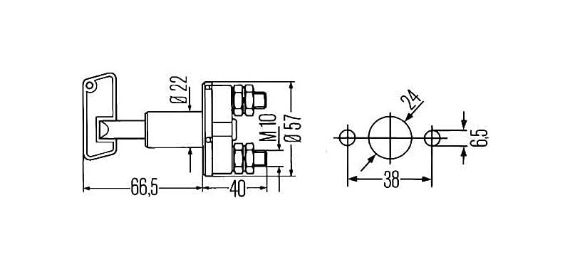
Figure 2: Technical drawing showing the dimensions of the Hella battery switch for mounting. This diagram provides measurements for the overall switch body, terminal spacing, and mounting hole pattern.
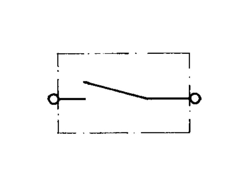
Figure 3: Basic electrical diagram illustrating the function of an on/off switch in a circuit. This shows a single-pole, single-throw (SPST) switch configuration.
5. Operating Instructions
The Hella 265-002843011 battery switch operates with a simple rotary mechanism using the provided red key.
- To Turn ON: Insert the red key into the switch and rotate it clockwise to the "ON" position. The key should lock into place, completing the electrical circuit.
- To Turn OFF: Rotate the red key counter-clockwise to the "OFF" position. The key can then be removed, breaking the electrical circuit and preventing unauthorized use or battery drain.
Note: Always ensure that the engine or any high-current devices are turned off before operating the battery switch to prevent potential damage to the switch or electrical system from arcing.
6. Maintenance
Regular maintenance ensures the longevity and reliable operation of your battery switch.
- Inspect Connections: Periodically check all cable connections to the switch terminals. Ensure they are clean, corrosion-free, and securely tightened. Loose connections can cause resistance, heat buildup, and potential failure.
- Clean the Switch: Wipe down the exterior of the switch with a damp cloth to remove dirt and grime. For marine applications, rinse with fresh water after exposure to saltwater to prevent salt buildup. Do not use harsh chemicals or abrasive cleaners.
- Check for Damage: Inspect the switch body and key for any signs of physical damage, cracks, or wear. Replace the switch if any significant damage is observed.
- Lubrication: The internal mechanism is generally maintenance-free. Avoid applying lubricants unless specifically recommended by the manufacturer.
7. Troubleshooting
| Problem | Possible Cause | Solution |
|---|---|---|
| No power to electrical system when switch is ON. |
|
|
| Switch feels stiff or difficult to turn. |
|
|
| Switch gets hot during operation. |
|
|
8. Specifications
| Attribute | Value |
|---|---|
| Brand | Hella |
| Model Number | 002843011 |
| Manufacturer | Hella KGaA Hueck & Co. |
| Product Dimensions (Overall) | Approx. 66.5 mm (Length) x 57 mm (Flange Diameter) |
| Flange Diameter | 2-1/4 inches (approx. 57 mm) |
| Item Weight | 149.69 grams |
| Material | Copper (contacts) |
| Operating Voltage | 24 Volts (DC) |
| Current Rating (Continuous) | 100 A |
| Max Load (Momentary Peak) | 1A @ 12V (1 sec), 5A @ 24V (1 sec) |
| Power | 2400 Watts (at 24V, 100A) |
| Switch Type | On/Off, 1-way, Rotary |
| Contact Type | Normally Open |
| Connector Type | Screw terminal (M10) |
| Mounting Type | Screw-on, Wall Mount Style |
| IP Rating | IP54 |
| Batteries Included/Required | No |
9. Warranty and Support
Specific warranty information for the Hella 265-002843011 On/Off Battery Switch is not provided in the product data. Please refer to the retailer or Hella's official website for the most up-to-date warranty details.
For technical support or inquiries, please contact Hella customer service through their official channels.
Hella Official Website: www.hella.com