Introduction
This shop manual, designated MF-42, provides detailed maintenance, service, and repair instructions for various Massey Ferguson tractor models. It covers both gasoline and diesel engine variants, offering comprehensive guidance for mechanics and owners.
Gasoline Models: MF230, MF235, MF245
Diesel Models: MF230, MF235, MF240, MF245, MF250
The manual includes essential wiring diagrams for all listed models, facilitating electrical system diagnostics and repairs.

Figure 1: Front cover of the Massey Ferguson Shop Manual MF-42, illustrating the models covered and the manual's purpose.
General Information and How to Use This Manual
This section provides important preliminary information for using the manual effectively, including details on tractor identification and measurement systems.
Tractor Identification
- The tractor serial number is stamped on a nameplate attached to the side of the instrument console.
- Diesel engine serial numbers are stamped on the right side of the cylinder block, near the fuel lift pump.
- Gasoline engine serial numbers are stamped on a plate attached to the left side of the cylinder block, above the distributor.
Dual Dimensions
This shop manual provides specifications in both Metric (SI) and U.S. Customary systems of measurement. The primary specification is given in the system perceived as preferred for servicing a particular component. The secondary specification, enclosed in parentheses, is the converted equivalent. For example, a specification of "0.28 mm (0.011 inch)" would indicate that the metric measurement is preferred, with the U.S. Customary equivalent provided for reference.

Figure 2: Index page of the manual, detailing the various systems covered and an explanation of dual dimensioning.
Maintenance and Repair Procedures
This section outlines detailed procedures for the inspection, adjustment, removal, overhaul, and reinstallation of various tractor components. Refer to the specific paragraphs for each procedure.
Brakes
- Disc Type: Refer to paragraph 173
- Assembly, R&R: Refer to paragraph 171
- Shoe Type: Refer to paragraph 175
Clutch (Engine)
- Adjustment: Refer to paragraph 110
- Dual Clutch: Refer to paragraph 113
- Split Torque Clutch: Refer to paragraph 112
- Tractor Split: Refer to paragraph 116
Differential
- Bevel Drive Gears: Refer to paragraph 163
- Differential Lock: Refer to paragraph 160
- R&R and Overhaul: Refer to paragraph 158
Electrical System
- Alternator & Regulator: Refer to paragraph 101
- Starter Motor: Refer to paragraph 107
- Wiring Diagrams: Refer to paragraph 239
Engine (Diesel)
- Assembly, R&R: Refer to paragraph 56
- Camshaft: Refer to paragraph 71
- Connecting Rods & Bearings: Refer to paragraph 72
- Cooling System: Refer to paragraph 76
- Crankshaft & Bearings: Refer to paragraph 77
- Cylinder Head: Refer to paragraph 57
- Oil Pump: Refer to paragraph 73
- Pistons, Sleeves & Rings: Refer to paragraph 73
- Timing Gears: Refer to paragraph 65
Engine (Gasoline)
- Assembly, R&R: Refer to paragraph 25
- Camshaft: Refer to paragraph 36
- Connecting Rods & Bearings: Refer to paragraph 40
- Cooling System: Refer to paragraph 50
- Crankshaft & Bearings: Refer to paragraph 41
- Cylinder Head: Refer to paragraph 26
- Governor: Refer to paragraph 48
- Oil Pump: Refer to paragraph 44
- Pistons, Sleeves & Rings: Refer to paragraph 38
- Timing Gears: Refer to paragraph 35
Front Axle
- Refer to paragraph 1
Fuel System (Diesel)
- Bleeding: Refer to paragraph 86
- Filters: Refer to paragraph 85
- Injector Nozzles: Refer to paragraph 89
- Injector Pump: Refer to paragraph 87
- Timing: Refer to paragraph 98
Fuel System (Gasoline)
- Carburetor: Refer to paragraph 46
Hydraulic System
- Adjustments: Refer to paragraph 194
- Auxiliary Pump: Refer to paragraph 202
- Auxiliary Valve: Refer to paragraph 235
- General: Refer to paragraph 184
- Lift Lever: Refer to paragraph 207
- Main Hydraulic Pump: Refer to paragraph 223
- Reservoir & Filter: Refer to paragraph 187
- System Checks: Refer to paragraph 186
- Trouble-Shooting: Refer to paragraph 186
Power Take-Off (Independent)
- Clutch Unit: Refer to paragraph 180
- Operation: Refer to paragraph 178
- Output Shaft: Refer to paragraph 179
Power Take-Off (Live)
- Ground Speed Gears: Refer to paragraph 176
- Output Shaft: Refer to paragraph 175
Rear Axle
- With Planetary Final Drive: Refer to paragraph 167
- Without Planetary Final Drive: Refer to paragraph 165
Steering System
- Hydrostatic Type: Refer to paragraph 18
- Manual Type: Refer to paragraph 3
- Power Assist Type: Refer to paragraph 6
Transmission
- Eight Speed: Refer to paragraph 127
- Manual Shuttle: Refer to paragraph 146
- Multi-Power: Refer to paragraph 145
- Six Speed: Refer to paragraph 119
Governor Adjustment (Paragraph 48)
For gasoline models, proper governor adjustment is crucial for engine performance. Begin by starting the engine and ensuring the ignition system is correctly set. The manual provides detailed diagrams and instructions for adjusting the throttle control linkage.

Figure 3: Excerpt from page 25, illustrating governor and throttle control linkage for adjustment procedures.
Hydraulic Lift Cover Removal (Paragraph 207)
To remove the hydraulic lift cover, first remove the seat and seat frame. Disconnect the upper lift links from the lift arms and remove the center link. On models equipped with a control beam, remove it from the control spring head. Finally, remove the side cover retaining screws and the side cover itself. Detailed diagrams assist in identifying components and proper removal sequence.
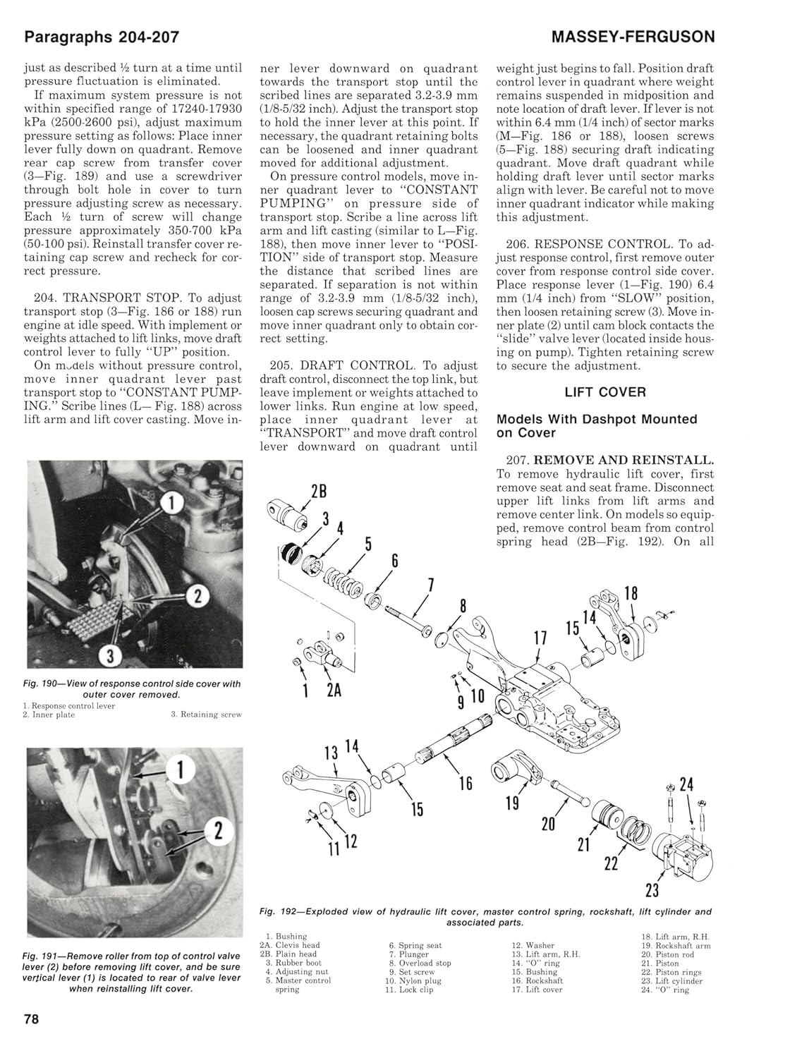
Figure 4: Excerpt from page 78, showing diagrams for the removal of the hydraulic lift cover and related components.
Troubleshooting
This manual integrates troubleshooting guidance within the specific repair sections for each system. For general hydraulic system issues, refer to paragraph 186 under the 'Hydraulic System' section. For electrical system diagnostics, consult the wiring diagrams provided in paragraph 239.
Manual Specifications
This section details the physical and publication specifications of this shop manual.
- Publisher: Haynes Manuals N. America, Inc.
- Publication Date: May 24, 2000
- Language: English
- Print Length: 96 pages
- ISBN-10: 0872884112
- ISBN-13: 978-0872884113
- Item Weight: 6.4 ounces
- Dimensions: 8.25 x 0.13 x 11 inches (21 x 0.33 x 27.94 cm)

Figure 5: Physical dimensions of the shop manual, highlighting its height.
Warranty Information
Specific warranty information for this shop manual is not provided within the product details. For inquiries regarding the manual's quality or content, please refer to the publisher's contact information.
Support
For further assistance or specific questions regarding the content of this Massey Ferguson Shop Manual, please contact the publisher:
Publisher: Haynes Manuals N. America, Inc.
Refer to the publisher's official website or contact channels for the most current support options.


