Anybus SP2980 Communicator PROFIBUS to Modbus RTU-Serial
 Preface
About This Document
This document describes how to install Anybus® Communicator™.
For additional documentation and software downloads, FAQs, troubleshooting guides and technical support, please visit www.anybus.com/support.
Document Conventions
DANGER
Instructions that must be followed to avoid an imminently hazardous situation which, if not avoided, will result in death or serious injury.
WARNING
Instructions that must be followed to avoid a potential hazardous situation that, if not avoided, could result in death or serious injury.
CAUTION
Instruction that must be followed to avoid a potential hazardous situation that, if not avoided, could result in minor or moderate injury.
IMPORTANT
Instruction that must be followed to avoid a risk of reduced functionality and/or damage to the equipment, or to avoid a network security risk.
Information Symbols
NOTE
Additional information which may facilitate installation and/or operation.
TIP
Helpful advice and suggestions.
Trademarks
Anybus® is a registered trademark of HMS Networks. All other trademarks are the property of their respective holders.
Safety
Intended Use
The intended use of this equipment is as a communication interface and gateway. The equipment receives and transmits data on various physical layers and connection types. If this equipment is used in a manner not specified by the manufacturer, the protection provided by the equipment may be impaired.
General Safety
CAUTION
Ensure that the power supply is turned off before connecting it to the equipment. This equipment contains parts that can be damaged by electrostatic discharge (ESD). Use ESD prevention measures to avoid damage. To avoid system damage, the equipment should be connected to ground.
IMPORTANT
Using the wrong type of power supply can damage the equipment. Ensure that the power supply is connected properly and of the recommended type.
Preparation
Cabling
Have the following cables available:
- Ethernet cable for configuration
- PROFIBUS cable for connecting to the high level network
- Power cable
Tools
Have the following tools available:
- Flat-head screwdriver, size 5.5 mm Needed when removing the Communicator from DIN-rail.
- Flat-head screwdriver, size 3 mm Needed when connecting the cables to the 7-pin connector.
Support and Resources
For additional documentation and software downloads, FAQs, troubleshooting guides and technical support, please scan the QR code to visit the Communicator support web page.
You can also visit www.anybus.comsupport and enter the product article number to search for the Communicator support web page. You find the product article number on the product cover.
Installation
DIN Rail Mounting
IMPORTANT
The equipment must be electrically grounded through the DIN rail for EMC compliance. Make sure that the equipment is correctly mounted on the rail and that the rail is properly grounded.
Figure 1. Attach the Communicator on the DIN rail
Connect to PROFIBUS Network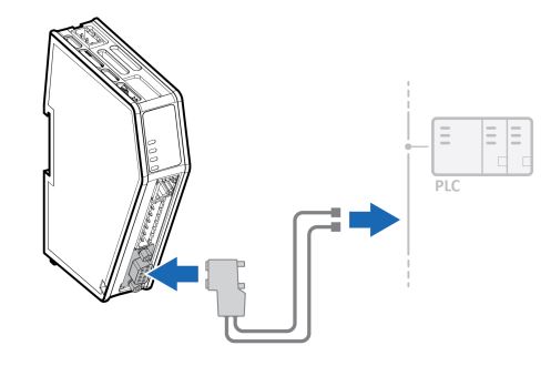
Figure 2. Connect to PROFIBUS network
| PROFIBUS Connector | Pin | Description |
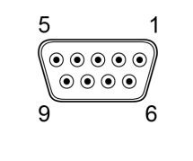
| 1 | Shield |
| 2 | Not used | |
| 3 | Line B | |
| 4 | RTS | |
| 5 | GND Bus | |
| 6 | +5 V Bus Out | |
| 7 | Not used | |
| 8 | Line A | |
| 9 | Not used | |
| Housing | PE |
Connect to Serial RS232/RS485 Subnetwork
NOTE
Use minimum 90 oC copper (Cu) wire only.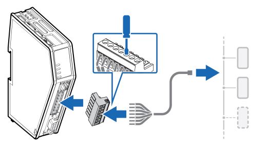 Figure 3. Connect to serial RS232/RS485 subnetwork
| 7-pin connector | Pin | Signal |
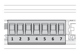 | 1 | RS232 Rx Input |
| 2 | RS232 Tx Output | |
| 3 | Functional Earth (FE) | |
| 4 | Signal GND | |
| 5 | RS485+ B | |
| 6 | RS485- A | |
| 7 | +5 V OUT |
Rotary Switch Settings
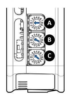
Rotary Switches Default Setting
By default, the value on the three rotary switches are set to 000.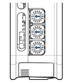
Figure 4. Rotary switches default setting 000.
Set a Node Address with Rotary Switches
About the Rotary Switch Settings
To set a node address for the PROFIBUS server, use the rotary switches located on the top front of the Communicator.
TIP
Use Windows Calculator (or similar application) to convert between hexadecimal (hex) and decimal (dec).
- The default node address setting is 000.
- When the node address setting is 000, you can sett the node address via the Communicator built-in web interface.
- The node address values are set in hexadecimal (hex).
- Minimum value is 00.
- Supports PROFIBUS node addresses 0-126 Dec (0-7E Hex).
- Each node address may only occur once in the network.
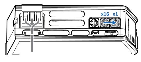
- The node address is read from the center rotary switch x16 to the front rotary switch x1.
- The rear rotary switch is not used, ensure that it is set to 0.
Before You Begin
Ensure that the Communicator is disconnected from power.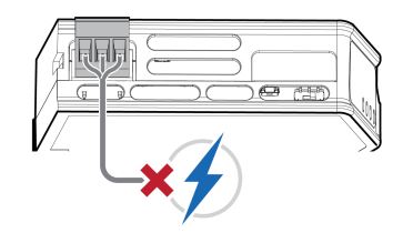
Figure 5. Disconnect Communicator from power
Procedure
Use a screwdriver to change the rotary switch position. Ensure that the rotary switches engage correctly.
Example 1. To set the node address 12 hex = 18 dec
- The rear rotary switch A is not used, ensure that it is set to 0.
- Set the center rotary switch B to 1 hex.
- Set the front rotary switch C to 2 hex.
The center rotary switch B 1 hex = 1 dec and the front rotary switch C 2 hex = 2 dec. The node address expressed in decimal numbers is therefore 16 x 1 + 2 = 18.
Example 2. To set the node address 7E hex = 126 dec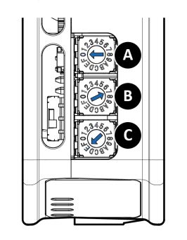
- If the rear rotary switch A is not used, ensure that it is set to 0.
- Set the center rotary switch B to 7.
- Set the front rotary switch C to E.
The center rotary switch B 7 hex = 7 dec and the front rotary switch C E hex = 14 dec. The node address expressed in decimal numbers is therefore 16 x 7 + 14 = 126.
To Do Next
Connect the Communicator to power. See Connect to Power (page 16).
Figure 6. Connect Communicator to power
Result
The set node address is active as soon as the Communicator is powered on.
NOTE
Changing the address settings on the rotary switches during operation is ignored. For a new address to take effect, power cycle the Communicator.
Connect to Power
CAUTION
Ensure that the power supply is turned off before connecting it to the equipment.
IMPORTANT
Using the wrong type of power supply can damage the equipment. Ensure that the power supply is connected properly and of the recommended type Before you connect the Communicator to power, ensure that the PROFIBUS address is set on the rotary switches. If the PROFIBUS address is set when the Communicator is operating, you must power cycle the Communicator for the new setting to take effect.
Figure 7. Connect to power
| Power port | Pin | Description |
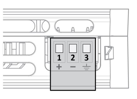 | 1 | 12-30 VDC Power Connector |
| 2 | Ground (GND) | |
| 3 | Functional Earth (FE) |
Security Switch
NOTE
After completing the configuration of the Communicator, lock the security switch to prevent unauthorized access to the Communicator built-in web interface.
When the security switch is in its locked position, the Communicator built-in web interface can not be accessed and the Communicator can not be configured using the built-in web interface. Network specific parameters, configured via the PLC is still available.
To Lock and Unlock the Security Switch
Figure 8. Security switch in locked and unlocked position
Use a pointed object, such as a ballpoint pen
- To lock the security switch, push the toggle towards the Communicator front.
- To unlock the security switch, push the toggle towards the Communicator back.
Security Switch Status LED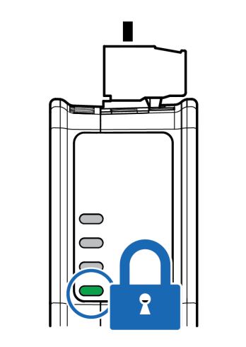
Figure 9. Security switch locked status LED
When the security switch is in its:
- locked position, the security switch status LED turn solid green.
- unlocked position, the security switch status LED is turned off.
Lock the Cables
Figure 10. Lock the cables
To strain relieve the cables, place a cable tie in the holder and lock the cables.
DIN Rail Demount
Before You Begin
IMPORTANT
Be careful when removing the Communicator from the DIN-rail. If not removed properly, the DIN rail locking mechanism and the product cover can break.
Have a flat-blade screwdriver, size 5.5 mm, available.
Procedure
Remove the Communicator from the DIN Rail:
- Insert the screwdriver into the Communicator DIN rail locking mechanism.
- To unlock the Communicator DIN rail locking mechanism, turn the screwdriver clockwise.

Figure 11. Unlock the Communicator
Hold the screwdriver in the DIN rail locking mechanism while you unhook the Communicator from the DIN rail.
Figure 12. Unhook the Communicator
Configuration
Connect to PC and Power
Figure 13. Connect to PC and Power
- Connect an Ethernet cable between the Communicator configuration port and your PC.
- Connect the Communicator to a power supply.
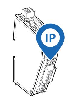
Find the Communicator on Your PC
The Communicator default IP address is 192.168.0.10. To be able to access the Communicator built-in web interface.
- Option 1| Set a static IP address on the PC
 On the PC accessing the Communicator built-in web interface, set a static IP address within the same IP address range as the Communicator IP address. To access the Communicator built-in web interface, ensure that port Port 80 TCP is open in your PC Windows Firewall. Note that when you change to a static IP address on your PC, internet access is lost.
 - Option 2 | Change the IP address on the Communicator configuration port
 Use the software application HMS IPconfig to find and change the IP address on the Communicator configuration port, to one within the same IP address range as the PC accessing the Communicator built-in web interface.
To download the installation files, please visit www.anybus.com/support and enter the product article number to search for the Communicator support web page. You find the product article number on the product cover.
Configure the Communicator
Figure 14. The Communicator built-in web interface Home page
Open the Communicator built-in web interface in HMS IPconfig or enter the Communicator IP address in your web browser. The built-in web interface takes you through the steps to configure the Communicator.
Support and Resources
If you need more in-depth information about the configuration, please visit www.anybus.com/support and enter the product article number to search for the Communicator support web page. You find the product article number on the product cover.
Technical Data
For complete technical specifications and regulatory compliance information, please visit www.anybus.com/support.
Technical Specifications
| Article identification | ABC3000-A |
| Communication connector | PROFIBUS DSUB connector |
| Configuration connector | RJ45 |
| Serial connector | 7-pin screw connector |
| Power connector | 3-pin screw connector |
| Power supply | 12-30 VDC, Reverse voltage protection and short circuit protection |
| Power consumption | Typical: 160 mA @ 24 V Max: 400 mA @ 12 V |
| Storage temperature | -40 to +85 °C |
| Operating temperature | -25 to +70 °C |
| Humidity | EN 600068-2-78: Damp heat, +40°C, 93% humidity for 4 days EN 60068-2-30: Damp heat, +25°C – +55°C, 95% RH, 2 cycles |
| Vibration | See datasheet |
| Housing material | Plastic, See datasheet for details |
| Protection class | IP20 |
| Product weight | 150 g |
| Dimensions | 27 x 144 x 98 mm (H x W x D) with connectors included |
| Mounting | DIN-rail |
For additional technical data and information related to the installation and use of this product, please visit www.anybus.com/support.
Communicator LED Indicators
NOTE
Before you can verify operation you must configure the Communicator.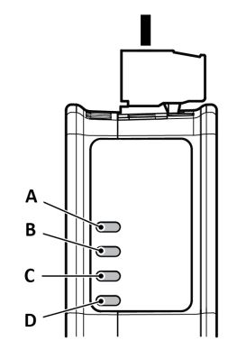
Figure 15. Communicator status (A), High level Network/Client (B), Subnetwork 2 (C) and (D) Security Switch
| LED A | LED B | LED C | LED D | |
| Operation Status | Gateway status | PROFIBUS | Subnetwork | Security switch |
| Off | No power | No data exchange | No power/ Exception/ Subnetwork not running/Node is switched off via a control word | No power/ Security switch is unlocked/ Exception/Fatal error |
| Green, flashing | Startup phase | Clear, data exchange | Running, one or more nodes are offline | N/A |
| LED A | LED B | LED C | LED D | |
| Operation Status | Gateway status | PROFIBUS | Subnetwork | Security switch |
| Green | Operational | Operate, data exchange | Running | Security switch is locked |
| Red | Exception/Fatal error | FATAL event | Fatal error | N/A |
| Red, one flash | Exception/Fatal error | Parameterization error | Fatal error | N/A |
| Red, two flash | Exception/Fatal error | PROFIBUS configuration error | Fatal error | N/A |
| Green/Red, flashing | Power up self- test/Firmware update/Firmware recovery | N/A | N/A | N/A |
Documents / Resources
 | Anybus SP2980 Communicator PROFIBUS to Modbus RTU-Serial [pdf] User Guide SP2980, Communicator PROFIBUS to Modbus RTU-Serial, SP2980 Communicator PROFIBUS to Modbus RTU-Serial |