Analog Devices DC3089A Dual 14A or Single 28A µModule Regulator PRODUCT
DESCRIPTION
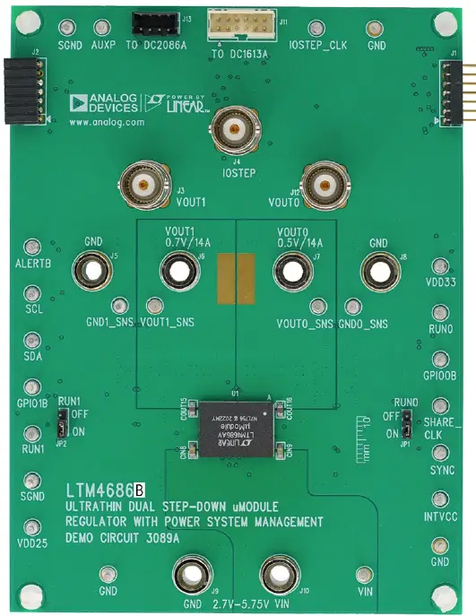
Demonstration circuit 3089A is a dual-output, high efficiency, high density, µModule regulator with 2.7V to 5.75V input range. Each output can supply 14A maximum load current. The demo board has a LTM4686B µModule regulator, which is a dual 14A or single 28A step-down regulator with digital power system management. Please see LTM4686B data sheet for more detailed information.
DC3089A powers up to default settings and produce power based on configuration resistors without the need for any serial bus communication. This allows easy evaluation of the DC/DC converter. To fully explore the extensive power system management features of the part, download the GUI software Powerplay™ onto your PC and use LTC’s I2C/SMBus/PMBus dongle DC1613A to connect to the board. LT powerplay allows the user to reconfigure the part on the fly and store the configuration in EEPROM, view telemetry of voltage, current, temperature and fault status.
GUI Download
The software can be downloaded from: lt powerplay
For more details and instructions of LT powerplay, please refer to LT powerplay GUI for LTM4686B Quick Start Guide.
Design files for this circuit board are available.
PERFORMANCE SUMMARY
Specifications are at TA = 25°C
|
PARAMETER |
CONDITIONS |
VALUE |
| Input Voltage Range | 2.7V to 5.75V | |
| Output Voltage, VOUT0 | VIN = 2.7-5.75V, IOUT0 = 0A to 14A | 0.5V to 3.6V, Default: 0.5V |
| Maximum Output Current, IOUT0 | VIN = 2.7-5.75V, VOUT0 = 0.5V to 3.6V | 14A |
| Output Voltage, VOUT1 | VIN = 2.7-5.75V, IOUT1 = 0A to 14A | 0.5V to 3.6V, Default: 0.7V |
| Maximum Output Current, IOUT1 | VIN = 2.7-5.75V, VOUT1 = 0.5V to 3.6V | 14A |
| Typical Efficiency | VIN = 5V, VOUT0 = 0.5V, IOUT0 = 14A | 73.5% (See Figure 5) |
| VIN = 5V, VOUT1 = 0.7V, IOUT1 = 14A | 78.2% (See Figure 6) | |
| Default Switching Frequency | 650kHz |
QUICK START PROCEDURE
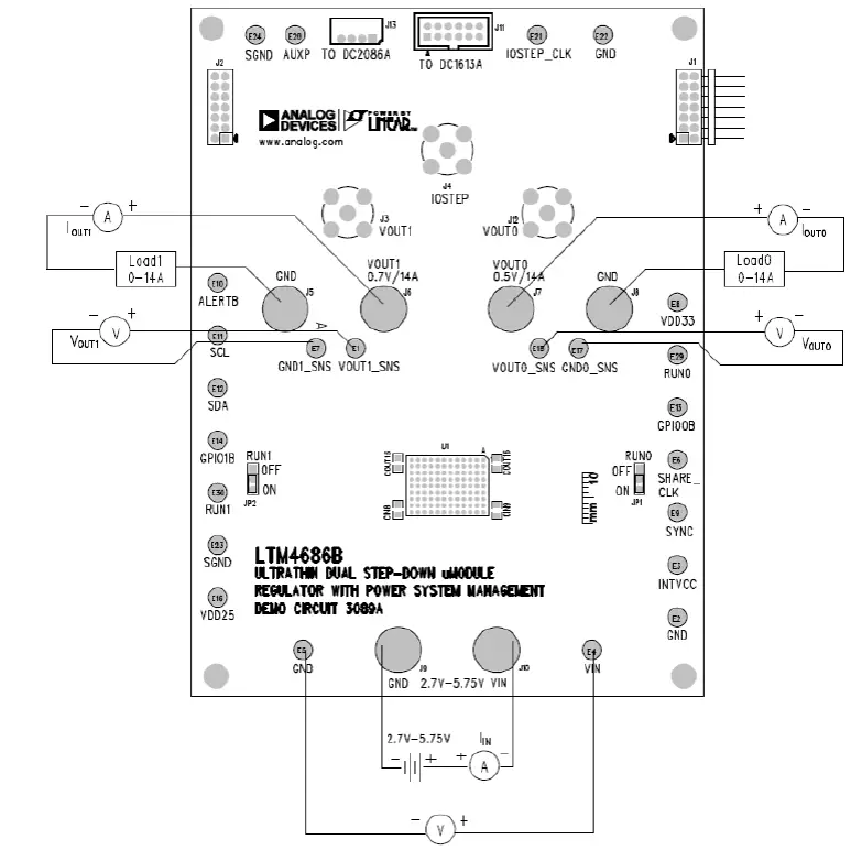
Demonstration circuit 3089A is easy to set up to evaluate the performance of the LTM4686B. Refer to Figure 2 for the proper measurement equipment setup and follow the procedure below.
- With power off, connect the input power supply to VIN (2.7V-5.75V*) and GND (input return).
- Connect the 0.5V output load between VOUT0 and GND (Initial load: no load).
- Connect the 0.7V output load between VOUT1 and GND (Initial load: no load).
- Connect the DVMs to the input and outputs. Set default jumper position: JP1: ON; JP2: ON.
- Turn on the input power supply and check for the proper output voltages. VOUT0 should be 0.5V ±0.5%, and VOUT1 should be 0.7V ±0.5%.
- Once the proper output voltages are established, adjust the loads within the operating range and observe the output voltage regulation, ripple voltage and other parameters.
- Connect the dongle and control the output voltages from the GUI. See “LT powerplay GUI for the LTM4686B Quick Start Guide” for details.
Note:
When measuring the output or input voltage rip-ple, do not use the long ground lead on the oscilloscope probe. See Figure 3 for the proper scope probe technique. Short, stiff leads need to be soldered to the (+) and (–) terminals of an output capacitor. The probe’s ground ring needs to touch the (–) lead and the probe tip needs to touch the (+) lead.
- – If 2.70V < VIN <5.50V, R9=OPEN, R91=R92=0ohm
- – If 4.50V < VIN < 5.75V,R9=0ohm, R91=R92=OPEN
Proper Measurement Equipment Setup
 Measuring Output Voltage Ripple
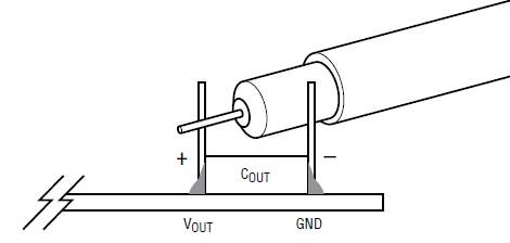
Connecting a PC to DC3089A
You can use a PC to reconfigure the power management features of the LTM4686B such as: nominal VOUT, mar-gin set points, OV/UV limits, temperature fault limits, sequencing parameters, the fault log, fault responses, GPIOs and other functionalities. The DC1613A dongle may be plugged when VIN is present.
Demo Setup with PC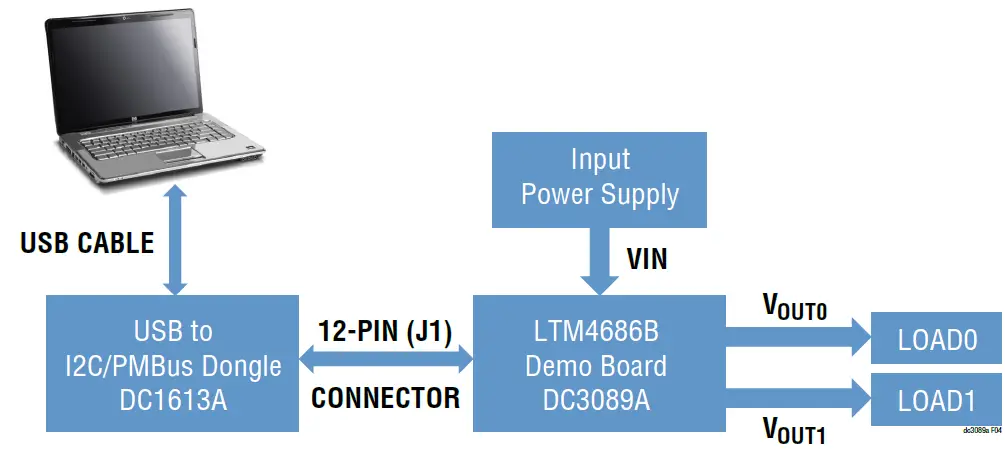 Figure 11. Thermal at VIN = 3.3V, VOUT0 = 0.5V, IOUT0 = 14A, VOUT1 = 0.7V, IOUT1 = 14A, TA = 25°C, No AirflowEfficiency vs Load Current on CH0
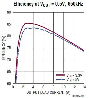 Efficiency vs Load Current on CH1
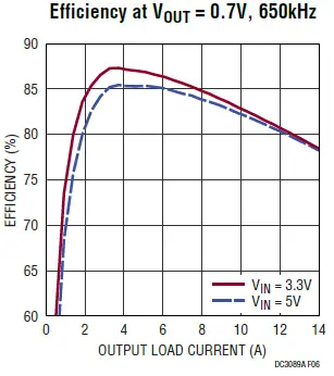 Output Voltage VOUT0 vs Load Current (VOUT0 = 0.5V)
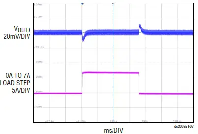 Output Voltage VOUT1 vs Load Current (VOUT1 = 0.7V)
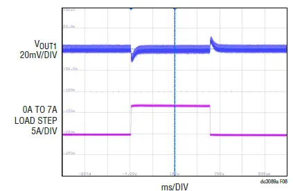 Output Voltage Ripple at VIN = 3.3V, VOUT0 = 0.5V, IOUT0 = 14A
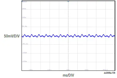 Output Voltage Ripple at VIN = 3.3V, VOUT1 = 0.7V, IOUT1 = 14A
 Thermal at VIN = 3.3V, VOUT0 = 0.5V, IOUT0 = 14A, VOUT1 = 0.7V, IOUT1 = 14A, TA = 25°C, No Airflow
LT POWERPLAY SOFTWARE GUI
LT powerplay is a powerful Windows based development environment that supports Linear Technology power system management ICs and μModules, including the LTM4675, LTM4676A, LTM4677, LTM4678, LTM4686, LTC3880, LTC3882 and LTC3883. The software supports a variety of different tasks. You can use LT powerplay to evaluate Linear Technology ICs by connecting to a demo board system. LT powerplay can also be used in an offline mode (with no hardware present) in order to build a multichip configuration file that can be saved and reloaded at a later time. LT powerplay provides unprecedented diagnostic and debug features. It becomes a valuable diagnostic tool during board bring-up to program or tweak the power management scheme in a system, or to diagnose power issues when bringing up rails. LT powerplay utilizes the DC1613A USB-to-SMBus controller to communicate with one of many potential targets, including the LTM4675, LTM4676A, LTM4677, LTM4686, LTC3880, LTC3882, LTC3883’s demo system, or a customer board. The software also provides an automatic update feature to keep the software current with the latest set of device drivers and documentation. The LT powerplay software can be downloaded from: lt powerplay
To access technical support documents for LTC Digital Power Products visit the LT powerplay Help menu. Online help also available through the LT powerplay.
LT powerplay Main Interface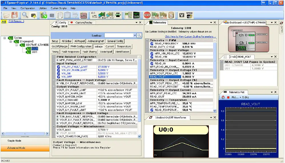
LTPOWERPLAY QUICK START PROCEDURE
The following procedure describes how to use LT powerplay to monitor and change the settings of LTM4686B.
- 1. Download and install the LT Powerplay GUI: lt powerplay
- Launch the LT powerplay GUI.
- The GUI should automatically identify the DC3089A. The system tree on the left-hand side should look like this:

- A green message box shows for a few seconds in the lower left hand corner, confirming that LTM4686B is communicating:

- In the Toolbar, click the “R” (RAM to PC) icon to read the RAM from the LTM4686B. This reads the configuration from the RAM of LTM4686B and loads it into the GUI.
- If you want to change the output voltage to a different value, like 0.6V. In the Config tab, type in 0.6 in the VOUT_COMMAND box, like this:
 Then, click the “W” (PC to RAM) icon to write these register values to the LTM4686B. After finishing this step, you will see the output voltage will change to 0.6V.
If the write is successful, you will see the following message:
- You can save the changes into the NVM. In the tool bar, click “RAM to NVM” button, as following:
- Save the demo board configuration to a (*.proj) file. Click the Save icon and save the file. Name it whatever you want.
- The GUI should automatically identify the DC3089A. The system tree on the left-hand side should look like this:
PARTS LIST
| ITEM | QTY | REFERENCE | PART DESCRIPTION |
MANUFACTURER, PART NUMBER |
Required Circuit Components
| 1 | 1 | CIN1 | CAP., 150µF, ALUM. ELECT., 35V, 20%, 8×10.2mm SMD, RADIAL, AEC-Q200 | PANASONIC, EEHZA1V151P |
| 2 | 0 | C16, C17 | CAP., OPTION, 0603 | |
| 3 | 2 | C2, C15 | CAP., 100pF, COG, 25V, 5%, 0603 | KEMET, C0603X101J3GACAUTO VISHAY, VJ0603A101JXXPW1BC AVX, 06033U101JAT2A |
| 4 | 6 | COUT1, COUT2, COUT3, COUT6, COUT7, COUT8 | CAP., 100µF, X5R, 6.3V, 20%, 1206 | AVX, 12066D107MAT2A KEMET, C1206C107M9PAC7800 KEMET, C1206C107M9PACTU MURATA, GRM31CR60J107ME39L NIC, NMC1206X5R107M6.3TRPLPF TDK, C3216X5R0J107M160AB |
| 5 | 2 | C1, C14 | CAP., 1500pF, X7R, 100V, 10%, 0603 | AVX, 06031C152KAT2A WURTH, 885012206109 |
| 6 | 4 | CIN2, CIN3, CIN4, CIN5 | CAP., 22µF, X5R, 25V, 10%, 1206 | AVX, 12063D226KAT2A MURATA, GRM31CR61E226KE15L SAMSUNG, CL31A226KAHNNNE YAGEO, CC1206KKX5R8BB226 |
| 7 | 8 | COUT4, COUT5, COUT9, COUT10, COUT11, COUT12, COUT13, COUT14 | CAP., 180µF, ALUM POLY, 4V, 20%, SMD, 7.3×4.3mm | PANASONIC, EEF-CT0G181R PANASONIC, EEFCT0G181R |
| 8 | 2 | CIN8, CIN9 | CAP., 2.2µF, X7R, 25V, 10%, 0805 | AVX, 08053C225KAT2A KEMET, C0805C225K3RACTU NIC, NMC0805X7R225K25TRPLPF TDK, C2012X7R1V225K125AE |
| 9 | 2 | COUT15, COUT16 | CAP., 47µF, X5R, 6.3V, 20%, 0805 | AVX, 08056D476KAT2A MURATA, GRM219R60J476ME44 |
| 10 | 3 | C21, C22, C24 | CAP., 1µF, X5R, 25V, 10%, 0603 | AVX, 06033D105KAT2A NIC, NMC0603X5R105K25TRPF TAIYO YUDEN, TMK107BJ105KA-T |
| 11 | 1 | C23 | CAP., 1µF, X7R, 25V, 10%, 0805 | AVX, 08053C105KAT2A WURTH, 885012207078 |
| 12 | 1 | C26 | CAP., 0.1µF, X5R, 25V, 10%, 0603 | AVX, 06033D104KAT2A SAMSUNG, CL10A104KA8NNNC TAIYO YUDEN, TMK107BJ104KA-T |
| 13 | 2 | C27, C28 | CAP., 0.01µF, X5R, 25V, 10%, 0603 | AVX, 06033D103KAT2A TDK, C1608X7R1E103K080AA |
| 14 | 2 | C29, C30 | CAP., 4.7µF, X5R, 16V, 10%, 0603 | AVX, 0603YD475KAT2A MURATA, GRM188R61C475KAAJD MURATA, GRM188R61C475KE11D TDK, C1608X5R1C475K080AC |
| 15 | 1 | C31 | CAP., 2.2µF, X7R, 10V, 10%, 0603 | AVX, 0603ZC225KAT2A MURATA, GRM188R71A225KE15D TDK, C1608X7R1A225K080AC YAGEO, CC0603KRX7R6BB225 |
| 16 | 0 | D1, D2 | DIODE, OPTION, SOD-323 | |
| 17 | 1 | D8 | DIODE, SCHOTTKY, 20V, 0.5A, SOD-882, LEADLESS | NEXPERIA, PMEG2005AEL, 315 |
| ITEM | QTY | REFERENCE | PART DESCRIPTION | MANUFACTURER, PART NUMBER |
| 18 | 24 | E1, E2, E3, E4, E5, E6, E7, E8, E9, E10, E11, E12, E13, E14, E15, E16, E17, E20, E21, E22, E23, E24, E29, E30 | TEST POINT, TURRET, 0.064 MTG. HOLE, PCB 0.062 THK | MILL-MAX, 2308-2-00-80-00-00-07-0 |
| 19 | 1 | J1 | CONN., HDR, MALE, 2×7, 2mm, R, A THT | MOLEX, 0877601416 MOLEX, 87760-1416 |
| 20 | 2 | JP1, JP2 | CONN., HDR., MALE, 1×3, 2mm, VERT, ST, THT | SULLINS CONNECTOR SOLUTIONS, NRPN031PAEN-RC |
| 21 | 1 | J2 | CONN., HDR, FEMALE, 2×7, 2mm, R, A THT | SULLINS CONNECTOR SOLUTIONS, NPPN072FJFN-RC |
| 22 | 3 | J3, J4, J12 | CONN., RF, BNC, RCPT, JACK, 5-PIN, ST, THT, 50Ω | AMPHENOL RF, 112404 |
| 23 | 6 | J5, J6, J7, J8, J9, J10 | CONN., BANANA JACK, FEMALE, THT, NON- INSULATED, SWAGE, 0.218 | KEYSTONE, 575-4 |
| 24 | 1 | J11 | CONN., HDR, SHROUDED, MALE, 2×6, 2mm, VERT, ST, THT | AMPHENOL, 98414-G06-12ULF FCI, 98414-G06-12ULF |
| 25 | 1 | J13 | CONN., HDR, SHROUDED, MALE, 1×4, 2mm, VERT, ST, THT | HIROSE ELECTRIC, DF3A-4P-2DSA |
| 26 | 1 | LB1 | LABEL SPEC, DEMO BOARD SERIAL NUMBER | BRADY, THT-96-717-10 |
| 27 | 4 | MH1, MH2, MH3, MH4 | STANDOFF, NYLON, SNAP-ON, 0.50 | KEYSTONE, 8833 |
| 28 | 1 | PCB | PCB, DC3089A | ADI APPROVED SUPPLIER, 600-DC3089A |
| 29 | 1 | Q1 | XSTR., MOSFET, N-CH, 40V, 14A, DPAK (TO-252) | VISHAY, SUD50N04-8M8P-4GE3 |
| 30 | 1 | Q19 | XSTR., MOSFET, P-CH, 30V, 3.5A, SOT23-3, AEC-Q101 | DIODES INC., DMP3130LQ-7 |
| 31 | 2 | R2, R22 | RES., 7.5k, 1%, 1, 10W, 0603 | VISHAY, CRCW06037K5FKEA |
| 32 | 13 | R3, R5, R7, R8, R25, R28, R32, R63, R65, R66, R91, R92, R93 | RES., 0Ω, 1, 10W, 0603, AEC-Q200 | NIC, NRC06ZOTRF VISHAY, CRCW06030000Z0EA VISHAY, CRCW06030000Z0EB |
| 33 | 0 | R6, R9, R23, R26, R28, R29, R31, R35, R38, R41, R42, R61, R62, R64, R67, R68, R74, R75, R83, R88, R89 | RES., OPTION, 0603 | |
| 34 | 12 | R10, R11, R12, R13, R14, R15, R16, R18, R19, R24, R52, R77 | RES., 10k, 1%, 1, 10W, 0603, AEC-Q200 | KOA SPEER, RK73H1JTTD1002F PANASONIC, ERJ3EKF1002V VISHAY, CRCW060310K0FKEA |
| 35 | 1 | R27 | RES., 12.7k, 1%, 1, 10W, 0603 | VISHAY, CRCW060312K7FKEA |
| 38 | 1 | R30 | RES., 0.787k, 1%, 1, 10W, 0603, AEC-Q200 | NIC., NRC06F7870TRF |
| 39 | 1 | R48 | RES., 0Ω, 3, 4W, 2010, AEC-Q200 | NIC, NRC50ZOTRF PANASONIC, ERJ12ZY0R00U VISHAY, CRCW20100000Z0EF |
| 40 | 0 | R49 | RES., OPTION, 2010 | |
| 41 | 0 | R50, R51 | RES., OPTION, 300Ω, 1%, 2512 |
| ITEM | QTY | REFERENCE | PART DESCRIPTION | MANUFACTURER, PART NUMBER |
| 42 | 1 | R53 | RES., 0.01Ω, 1%, 1W, 2010, SENSE | IRC, LRC-LRF2010LF-01-R010-F TT ELECTRONICS, LRC-LRF2010LF-01-R010-F |
| 43 | 2 | R72, R73 | RES., 4.99k, 1%, 1, 10W, 0603, AEC-Q200 | NIC, NRC06F4991TRF PANASONIC, ERJ3EKF4991V VISHAY, CRCW06034K99FKEA |
| 44 | 1 | R78 | RES., 15.8k, 1%, 1, 10W, 0603, AEC-Q200 | NIC, NRC06F1582TRF PANASONIC, ERJ3EKF1582V VISHAY, CRCW060315K8FKEA |
| 45 | 2 | R69, R70 | RES., 10Ω, 1%, 1, 1/10W, 0603 | NIC, NRC06F10R0TRF PANASONIC, ERJ3EKF10R0V VISHAY, CRCW060310R0FKEA |
| 46 | 0 | R82 | RES., OPTION, 1206 | |
| 47 | 2 | STNCL1 | TOOL, STENCIL, 700-DC3089A | ADI APPROVED SUPPLIER, 830-DC3089A |
| 48 | 1 | U1 | IC, DUAL 10A OUTPUTS STEP-DOWN, µModule REGULATOR, BGA | ANALOG DEVICES, LTM4685EV#PBF |
| 49 | 1 | U3 | IC, MEMORY, EEPROM, 2Kb (256×8), TSSOP-8, 400kHz | MICROCHIP, 24LC025-I, ST MICROCHIP, 24LC025T-I, ST |
| 50 | 1 | U6 | IC, LOW NOISE REGULATED CHARGE, PUMP IN, 2×2 DFN | ANALOG DEVICES, LTC3204BEDC-5#PBF |
| 51 | 2 | XJP1, XJP2 | CONN., SHUNT, FEMALE, 2-POS, 2mm | SAMTEC, 2SN-BK-G |
SCHEMATIC DIAGRAM


Legal Terms and Conditions
By using the evaluation board discussed herein (together with any tools, components documentation or support materials, the “Evaluation Board”), you are agreeing to be bound by the terms and conditions set forth below (“Agreement”) unless you have purchased the Evaluation Board, in which case the Analog Devices Standard Terms and Conditions of Sale shall govern. Do not use the Evaluation Board until you have read and agreed to the Agreement. Your use of the Evaluation Board shall signify your acceptance of the Agreement. This Agreement is made by and between you (“Customer”) and Analog Devices, Inc. (“ADI”), with its principal place of business at One Technology Way, Norwood, MA 02062, USA. Subject to the terms and conditions of the Agreement, ADI hereby grants to Customer a free, limited, personal, temporary, non-exclusive, non-sublicensable, non-transferable license to use the Evaluation Board FOR EVALUATION PURPOSES ONLY. Customer understands and agrees that the Evaluation Board is provided for the sole and exclusive purpose referenced above, and agrees not to use the Evaluation Board for any other purpose. Furthermore, the license granted is expressly made subject to the following additional limitations: Customer shall not (i) rent, lease, display, sell, transfer, assign, sublicense, or distribute the Evaluation Board; and (ii) permit any Third Party to access the Evaluation Board. As used herein, the term “Third Party” includes any entity other than ADI, Customer, their employees, affiliates and in-house consultants. The Evaluation Board is NOT sold to Customer; all rights not expressly granted herein, including ownership of the Evaluation Board, are reserved by ADI. CONFIDENTIALITY. This Agreement and the Evaluation Board shall all be considered the confidential and proprietary information of ADI. Customer may not disclose or transfer any portion of the Evaluation Board to any other party for any reason. Upon discontinuation of use of the Evaluation Board or termination of this Agreement, Customer agrees to promptly return the Evaluation Board to ADI. ADDITIONAL RESTRICTIONS. Customer may not disassemble, decompile or reverse engineer chips on the Evaluation Board. Customer shall inform ADI of any occurred damages or any modifications or alterations it makes to the Evaluation Board, including but not limited to soldering or any other activity that affects the material content of the Evaluation Board. Modifications to the Evaluation Board must comply with applicable law, including but not limited to the RoHS Directive. TERMINATION. ADI may terminate this Agreement at any time upon giving written notice to Customer. Customer agrees to return to ADI the Evaluation Board at that time. LIMITATION OF LIABILITY. THE EVALUATION BOARD PROVIDED HEREUNDER IS PROVIDED “AS IS” AND ADI MAKES NO WARRANTIES OR REPRESENTATIONS OF ANY KIND WITH RESPECT TO IT. ADI SPECIFICALLY DISCLAIMS ANY REPRESENTATIONS, ENDORSEMENTS, GUARANTEES, OR WARRANTIES, EXPRESS OR IMPLIED, RELATED TO THE EVALUATION BOARD INCLUDING, BUT NOT LIMITED TO, THE IMPLIED WARRANTY OF MERCHANTABILITY, TITLE, FITNESS FOR A PARTICULAR PURPOSE OR NONINFRINGEMENT OF INTELLECTUAL PROPERTY RIGHTS. IN NO EVENT WILL ADI AND ITS LICENSORS BE LIABLE FOR ANY INCIDENTAL, SPECIAL, INDIRECT, OR CONSEQUENTIAL DAMAGES RESULTING FROM CUSTOMER’S POSSESSION OR USE OF THE EVALUATION BOARD, INCLUDING BUT NOT LIMITED TO LOST PROFITS, DELAY COSTS, LABOR COSTS OR LOSS OF GOODWILL. ADI’S TOTAL LIABILITY FROM ANY AND ALL CAUSES SHALL BE LIMITED TO THE AMOUNT OF ONE HUNDRED US DOLLARS ($100.00). EXPORT. Customer agrees that it will not directly or indirectly export the Evaluation Board to another country, and that it will comply with all applicable United States federal laws and regulations relating to exports. GOVERNING LAW. This Agreement shall be governed by and construed in accordance with the substantive laws of the Commonwealth of Massachusetts (excluding conflict of law rules). Any legal action regarding this Agreement will be heard in the state or federal courts having jurisdiction in Suffolk County, Massachusetts, and Customer hereby submits to the personal jurisdiction and venue of such courts. The United Nations Convention on Contracts for the International Sale of Goods shall not apply to this Agreement and is expressly disclaimed.
Documents / Resources
 |
Analog Devices DC3089A Dual 14A or Single 28A µModule Regulator [pdf] User Manual DC3089A Dual 14A or Single 28A Module Regulator, DC3089A, Dual 14A or Single 28A Module Regulator, Single 28A Module Regulator, Module Regulator, Regulator |


