![]()
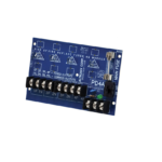
VB Series
Power Boosters
Installation Guide
Overview:
The unit converts a 12VDC-24VDC input into a regulated 24VDC ouput.
| Altronix Model Number | Output | Input | Cable Assembly | Terminal Block |
| VB1 | 24VDC @ 0.75A | 12VDC – 24VDC | √ | – |
| VB1T | 24VDC @ 0.75A | 12VDC – 24VDC | – | √ |
Specifications:
Input:
- 12VDC-24VDC input.
Output:
- 24VDC @ 0.75A.
- Electronically filtered and regulated output.
- Built-in overload protection.
LED Indicators:
- Power LED.
Applications:
- Compensates for voltage drop due to long wire runs.
Applications (cont’d):
- Power for 24VDC Access Control devices from a 12VDC power source.
Mechanical:
- High-impact insulated housing.
- Compact design allows for integration in a wide range of camera housings.
Dimensions (L x W x H approx.):
1.625” x 2.375” x 1” (41.3mm x 60.3mm x 25.4mm).

Installation Instructions:
- Mount the unit in the desired location.
- a. VB1: Connect Yellow (positive) lead and Purple (negative) lead to 12VDC to 24VDC source. Observe polarity.
b. VB1T: Connect 12VDC to 24VDC source to the terminals marked [Input +] and [Input –]. - Measure output voltage and check polarity before connecting devices in order to avoid potential damage.
- a. VB1: Connect Red lead [Pos. +] and Black lead [Neg. –] to 24VDC device to be powered.
b. VB1T: Connect 24VDC device to be powered to terminals marked [+ DC –]. - LED will illuminate when power is present.
![]()
Altronix is not responsible for any typographical errors.
140 58th Street, Brooklyn, New York 11220 USA | phone: 718-567-8181 | fax: 718-567-9056
web site: www.altronix.com | e-mail: info@altronix.com | Lifetime Warranty
IIVRseries – Rev. 081004
F23U
Documents / Resources
 | Altronix VB Series Power Voltage Boosters [pdf] Installation Guide VB Series, Power Voltage Boosters, Voltage Boosters, Power Boosters, VB Series, Boosters |