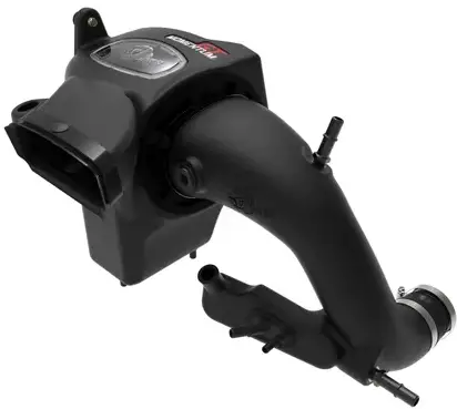
aFe POWER WRX Advanced Flow Engineering Cold Air Intake System
Product Specifications
- Make: Subaru
- Model: WRX
- Year: 2022-2024
- Engine: H4-2.4L (t)
Product Usage Instructions
Removal
- Step 1: Using a panel clip remover, remove the two clips securing the air intake scoop.
- Step 2: Remove the air intake scoop and set it aside with the clips.
INTRODUDCTION
 Please read the entire instruction manual before proceeding.
- Ensure all components listed are present.
- For technical support, please call 9514937185.
- Ensure you have all necessary tools before proceeding.
- Do not attempt to work on your vehicle when the engine is hot.
- Retain factory parts for future use.
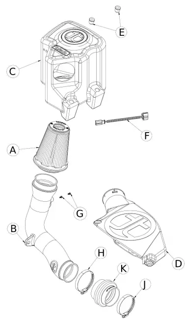
Parts Description
| Label | Qty. | Description | Part Number |
| A1 | 1 | Air Filter (Pro 5R) | TF-9029R |
| A2 | 1 | Air Filter (Pro DRY S) | TF-9029D |
| B | 1 | Intake Tube | 05-5670064B1 |
| C | 1 | Housing | 05-5670064B2 |
| D | 1 | Scoop | 05-5670064B3 |
| E | 2 | Plug, 3/4″ ID | 05-01746 |
| F | 1 | Harness, MAF Extension: 6″ 4-Wire | 05-70045 |
| G | 2 | Screw, Torx: M4x8mm | 03-50491 |
| H | 1 | Clamp, 048 (2-9/16″ – 3-1/2 “) | 03-50007 |
| J | 1 | Clamp, 044 (2-5/16″ – 3-1/4″) | 03-50019 |
| K | 1 | Coupling, Silicone Bellows Rdr (3”x3-1/8”)ID x 3″ L | 05-01400 |
Installation will require the following tools:
- Panel clip remover, T-20 Torx driver, 8mm nut driver, #2 Phillips screwdriver, 10mm socket, driver, and extensions, 10mm open wrench
Warranty Information
- Warranty Information available at https://afepower.com/contact#warranty
Emissions Disclaimer:
- This product is not currently CARB exempt and is not available for purchase in California or for use on any vehicle registered with the California Department of Motor Vehicles.
INSTALLATION INSTRUCTION
REMOVAL
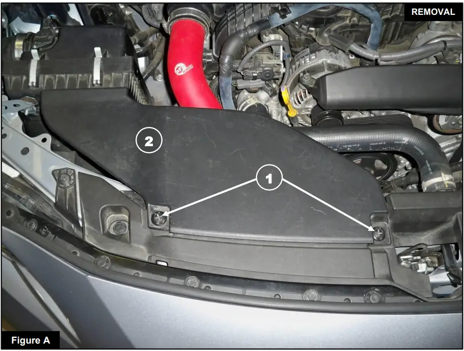
Refer to Figure A for Steps 1-2
- Step 1: Using a panel clip remover, remove the two clips 1 that secure the air intake scoop 2.
- Step 2: Remove the air intake scoop and set it aside with the clips.
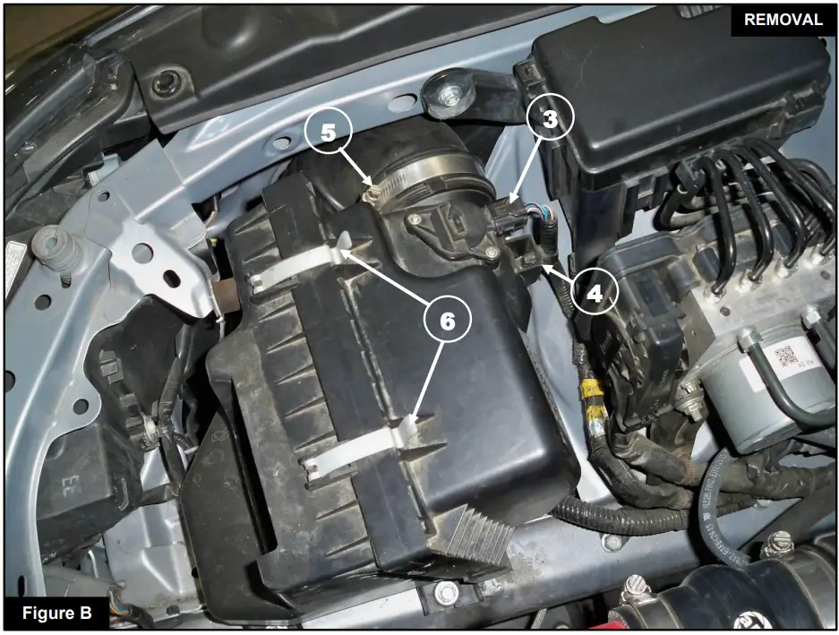
Refer to Figure B for Steps 3-6
- Step 3: Disconnect the MAF sensor 3 and remove the clip 4 securing the harness.
- Step 4: Using an 8mm nut driver, loosen the clamp 5 at the factory airbox.
- Step 5: Disconnect the factory intake tube from the factory airbox.
- Step 6: Remove the clips 6 from the factory airbox and remove the rear section of the factory airbox with the air filter.
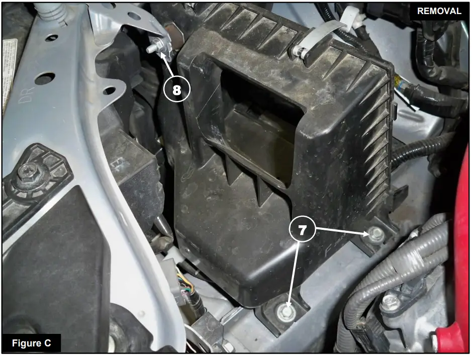
Refer to Figure C for Steps 7-9
- Step 7: Using a 10mm socket and driver, remove the two screws 7 holding the factory airbox. Step 8: Using a 10mm open wrench, remove the nut 8 holding the factory airbox.
- Step 9: Remove the front half of the factory airbox.
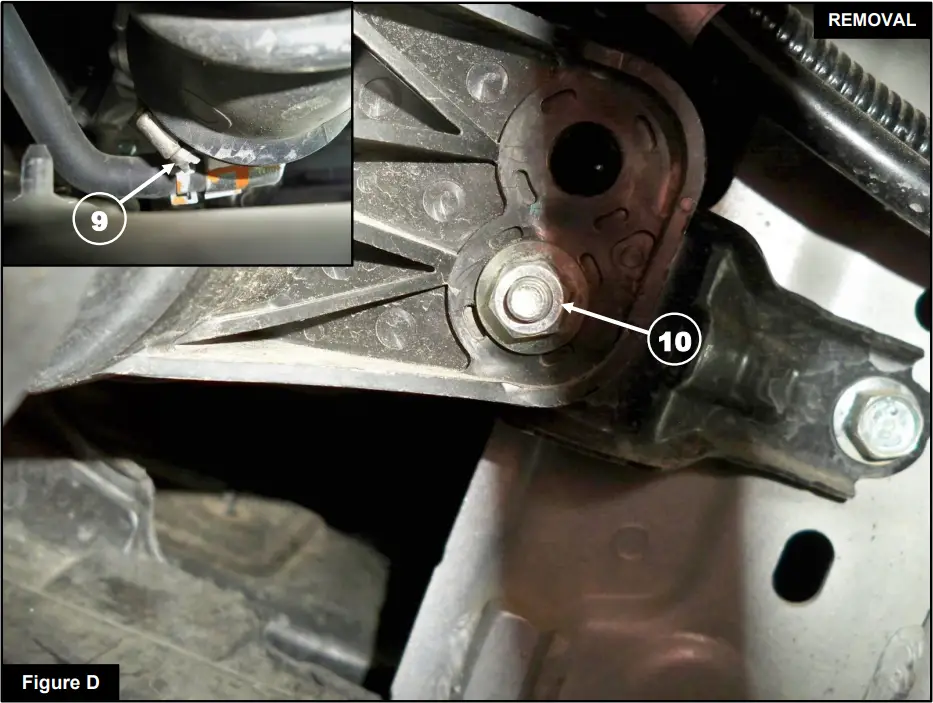
Refer to Figure D for Steps 10-12
- Step 10: Using an 8mm nut driver, loosen the clamp 9 at the turbo inlet (this may need to be done from underneath the vehicle to make it easier to access).
- Step 11: Using a 10mm socket and driver, remove the nut 10 securing the factory intake tube.
- Step 12: Remove the factory intake tube.
INSTALL
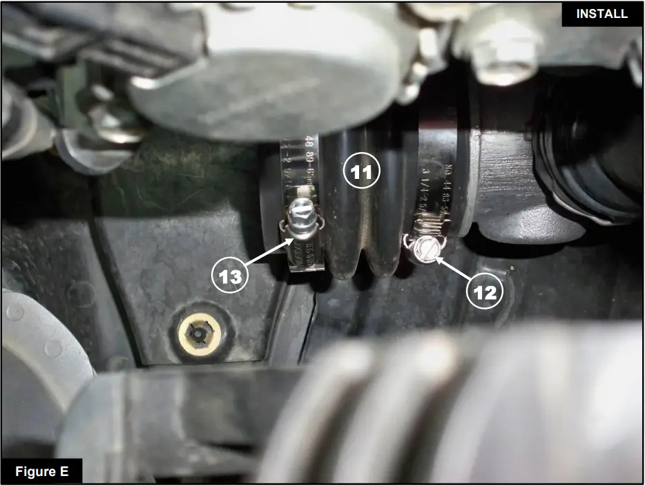
Refer to Figure E for Steps 13-14
- Step 13: Install the supplied coupling (05-01400) 11 with the smaller diameter side on the turbo inlet using the supplied #44 clamp 12 and tighten the clamp using an 8mm nut driver.
- Step 14: Place the supplied #48 clamp 13 onto the other end of the coupling, but do not tighten it at this time.
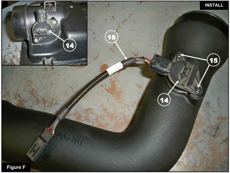
Refer to Figure F for Steps 15-17
- Step 15: Using a #2 Phillips head screwdriver, remove the MAF sensor 14 from the factory airbox.
- Step 16: Use a Torx T20 driver to install the MAF sensor on the Takeda intake tube with the supplied M4screws 15.
- Step 17: Connect the provided MAF harness extension 16 to the MAF sensor.
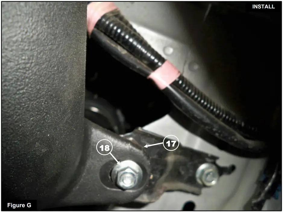
Refer to Figure G for Steps 18-21
- Step 18: Install the Takeda intake tube into the coupling first, and snug but do not tighten the clamp.
- Step 19: Attach the rubber isolator stud 17 through the mounting tab on the Takeda intake tube.
- Step 20: Secure the Takeda intake tube using the nut 18 removed in Step 11 and tighten the nut using a 10mm socket and driver.
- Step 21: Using an 8mm nut driver, tighten the clamp at the coupling.
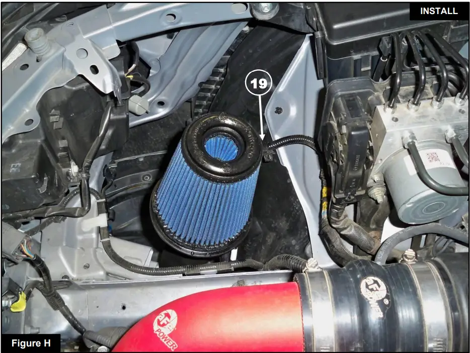
Refer to Figure H for Steps 22-23
- Step 22: Install the Takeda filter with the clamp onto the Takeda intake tube. Tighten the clamp using an 8 mm nut driver.
- Step 23: Connect the MAF harness extension to the factory harness 19.
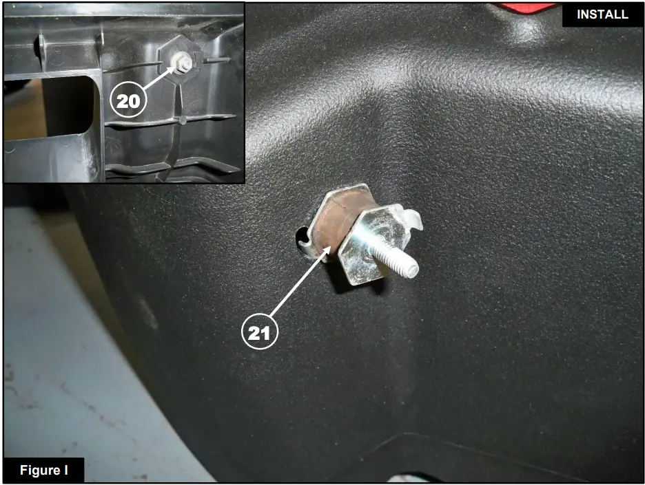
Refer to Figure I for Steps 24-25
- Step 24: Using a 10mm socket and driver, remove the nut 20 attaching the rubber isolator 21 to the factory airbox.
- Step 25: Transfer the rubber isolator and nut to the Takeda housing as shown.
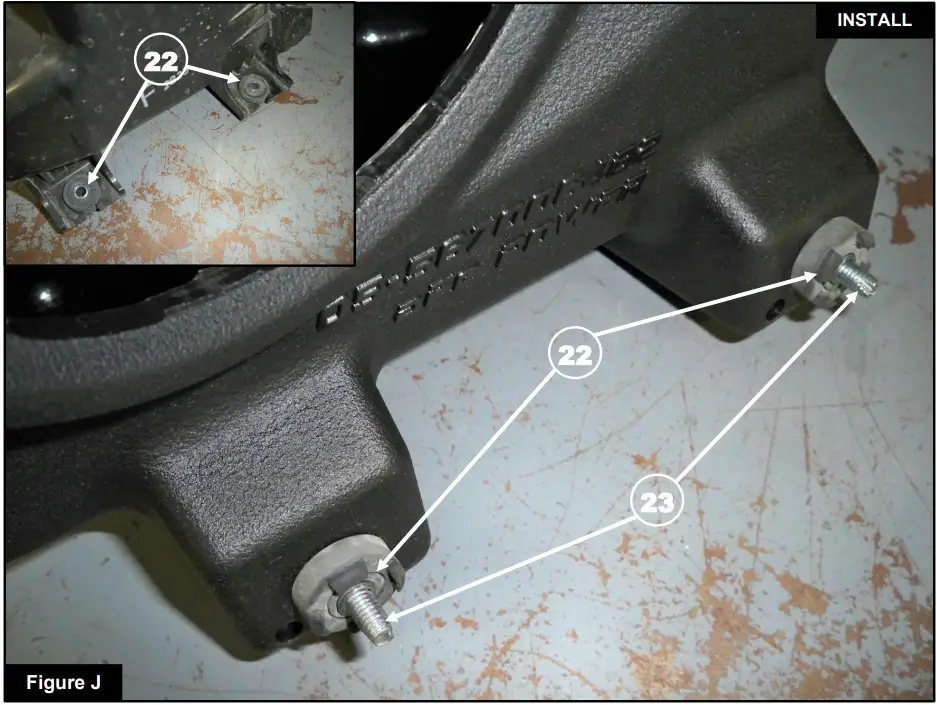
Refer to Figure J for Steps 26-28
- Step 26: Remove the metal sleeves and isolators 22 from the factory airbox. Note that the thicker side of the isolator faces the bottom of the housing.
- Step 27: Installl the metal sleeves and isolators into the Takeda housing as shown.
- Step 28: Install the two screws 23 removed on Step 7, through to the metal sleeves and isolators from the inside the Takeda housing.
Refer to Figure K for Steps 29-33
- Step 29: Install the Takeda housing onto the Takeda air filter and ensure the filter snaps in place.
- Step 30: Install the stud from the rubber isolator through the bracket hole as shown and install the nut 24 removed in Step 8. Do not fully tighten at this point.
- Step 31: Using a 10mm socket, extension, and driver, install the screws removed in Step 7. Use the screw access holes 25 to secure the Takeda housing in place with the two mounting screws.
- Step 32: Plug the screw access holes with the supplied plugs 26.
- Step 33: Tighten the rubber isolator nut.

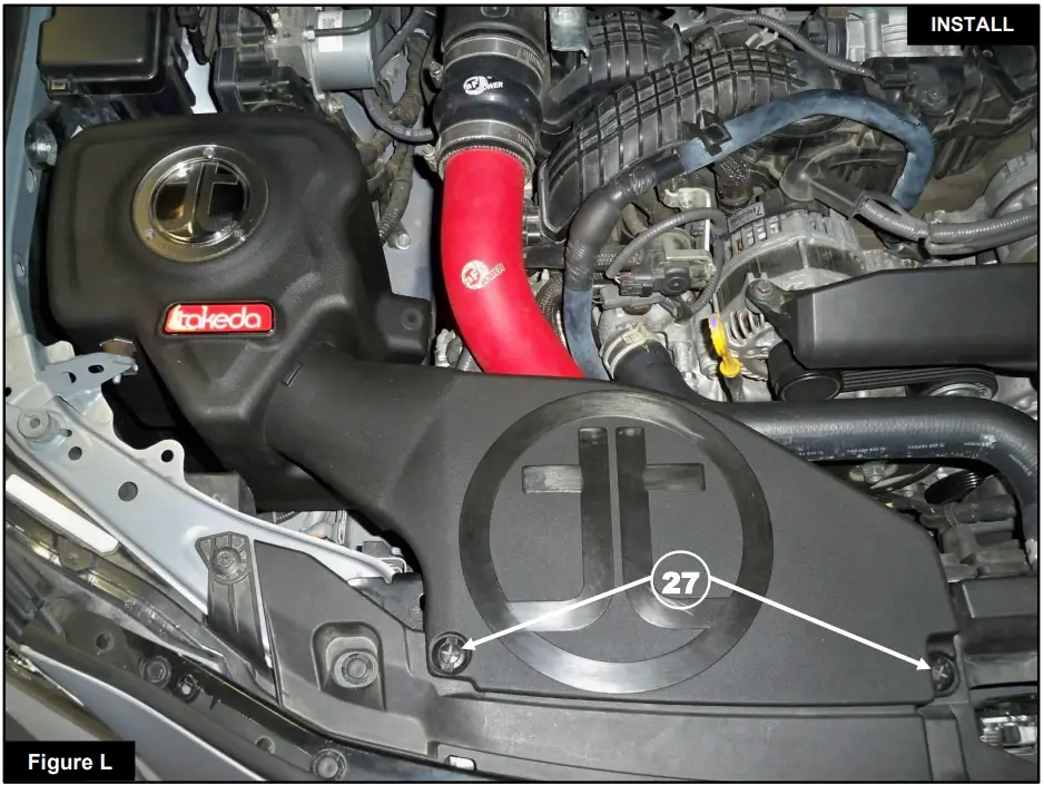
Refer to Figure L for Steps 34-35
- Step 34: Install the Takeda air intake scoop using the clips 27 removed in Step 1.
- Step 35: Check that all the components are tight and secure. Your installation is now complete. Thank you for choosing aFe POWER!
- NOTE: Check all bolts, clamps, and connectors after 100-200 miles.
- advanced FLOW engineering. inc.
- Corona, CA 92879
- https://afepower.com/contact
Frequently Asked Questions
- Q: Is this product CARB compliant?
- A: No, this product is not currently CARB exempt and is not available for purchase in California or for use on any vehicle registered with the California Department of Motor Vehicles.
- Q: Where can I find warranty information for this product?
- A: Warranty Information is available at https://afepower.com/contact#warranty
Documents / Resources
 | aFe POWER WRX Advanced Flow Engineering Cold Air Intake System [pdf] Instruction Manual 56-70064R, 56-70064D, WRX Advanced Flow Engineering Cold Air Intake System, WRX Advanced Flow Engineering Intake System, Cold Air Intake System, Cold Intake System, Air Intake System, Intake System, Intake |


