aerauliqa EHS Range Ceiling High Volume Low
Speed Fan Instruction Manual
1 GENERAL INFORMATION
Carefully read the instructions contained in this manual. This Specific Manual MUST be read in conjunction with the “Installation, Operation and Maintained General Manual”. Note: store the manual for future reference. We reserve the right to improve and make changes to the manual, products and accessories without any obligation to update previous productions and manuals.
The installation and service of the unit and complete ventilation system must be performed by an authorized installer and in accordance with local rules and regulation.
2 PRECAUTIONS
In addition to the precautions indicated in the “Installation, Operation and Maintenance General Manual” special attention should be paid to the following warning notes:
-The fan must be installed at a height of not less than 2.7m from the floor below. Installation at a lower height is considered “improper use”. In case of “improper use” the manufacturer declines all responsibility for any damage that may be caused to persons or property, and any warranty will be considered invalid.
RECOMMENDED BOLT TORQUE FOR COARSE THREADED METRIC STEEL BOLTS TE-TCEI GRADE 8.

– fixing: check/inspect and eventually retighten all the fixing annually.
– windy conditions: fans should not operate in case of strong wind (6m/s) and should not be installed in places where it is frequently windy.
– weight: it is recommended that the building structure is capable to bear approx. twice the weight of the fan as well as a torque of at least 350Nm. A professional structural engineer should perform an evaluation before installing the fan.
– key safety features: make sure that all the supplied key safety features are used to install the fan to provide a comprehensive protection of people, animals, equipment’s and property. The installer and the building owner are responsible to ensure the safety of the fan mounting system and that the fan installation is correct, in compliance with any national and local regulations.
3 TYPE
Ceiling fans with EC brushless motor designed for industrial, civil and zootechnical applications, where high performance with low rotation speed are required.
4 MAIN FEATURES
- Brushless motor 200-480Vac, 3ph, 50/60Hz, IP65
- Max temperature +50°C
- Speed controllable
- Suitable for S1 continuous service
- Embedded electronic system
- Anodized extruded blades
- Gearless for silent operation
- Maintenance-free
- Key Safety features
- Simplified electrical wiring connection: pre cabled
- Strong and robust design and manufacturing
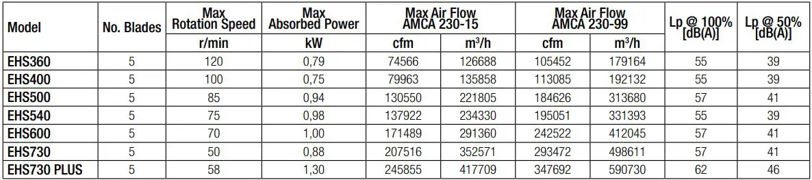
5 DATI @400Vac, 50Hz
6 DIMENSIONS AND CLEARANCES

7 COMPONENTS
- The fan is delivered split into two kits, each one in its own box. · MOTOR KIT includes:
– main body ((Fig.VII and VIII – 15).
– standard 800mm length downrod (Fig.II, III and VIII- 6).
– 2x ceiling fixing brackets (Fig.III, IV and V – 7).
– 2x fixings sets:
– 4x M12 bolts (Fig.III e VIII – 8), 4x locknuts (Fig.III e VIII – 9), 4x standard washers (Fig.III e VIII – 10 ) and 4x spring washers (Fig.III e VIII – 11), for fan fixing to the ceiling.
– 10x M8 flange bolts (Fig.XIV – 20), 10x locknuts (Fig.XIV – 21), 10x spring washers (Fig.XIV – 22) and 10x plastic caps (Fig.XIV – 23), for blades fixing to main body.
– plastic components set: hub cover (Fig.XV – 24), 5x M4 bolts (Fig.XV – 25), canopy (Fig. VI – 13) and 4x self-tapping screw (Fig.VI – 14).
– security wires set: 1x Ø5mm 2,5m security wire with one ring (Fig.I, II and V- 1), 2x Ø5mm 0,35m wire with two rings (Fig.I and X – 3), 2x clamp 5mm (Fig.V – 12), 2x 7mm snap-hook (Fig.I e X – 4), 1x shackle (Fig.I – 2) for the security wire, 4x Ø3mm 2,5m stabilizing wires with turnbuckle (Fig.XI – 16), 4x 5mm snap-hooks (Fig.XI – 17) and 8x 3mm clamp (Fig.XIII – 18) for the stabilizing wires. - BLADES KIT incudes five blades with mounted terminals (Fig.XIV – 19).
- The electrical wire type (Fig.II, IX and XVI – 5) must comply with the local regulations of the electric system and must have the following features:
– 4 core supply power cable (one cable section 1mm2)
– 8 core control cable (one cable section 0.5mm2)
Note: the voltage drop cannot be higher than 4%.
8 INSTALLATION
- Decide on the position the fan is to be sited keeping in consideration as follows:
– the minimum distance from the floor to the lowest point of the fan is 2,7m.
– the minimum distance from the fan blade to the side wall of similar obstruction depends on the fan model (§ 6 – C).
– avoid mounting the fan directly below lights to prevent any strobe effect caused by the moving blades.
– in any installation where fire sprinklers are placed, fan should not interfere with their operation.
– fan should not be placed near to supply air outlet or exhausting inlets of other HVAC equipment which could decrease the fan capacity and compromise the indoor air quality as well as the occupants’ comfort:
– supply air outlet should deliver air away from the unit.
– exhaust fan inlets or other return air point which could create negative pressure should not be located within 1,5 times the fan diameter.
– when mounting the fan, mark the floor with a large crosshatched circle to alert people of the overhead fan location.


9 WIRING DIAGRAM
- Make sure that the mains supply to the unit is disconnected before performing any installation, service, maintance or electrical work!
- The installation and service of the unit and complete ventilation system must be performed by an authorized installer and in accordance with local rules and regulations.
- Fan must be earthed.
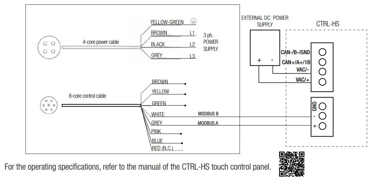
WARNING: regardless of the control system in place (potentiometer or ModBus), it’s strongly recommended to wire the ModBus communication line and make it accessible from ground level, in order to ease troubleshooting via ModBus anytime after the installation.
9.1 CTRL-A (accessory on request)

9.2 CTRL-HS (accessory on request)
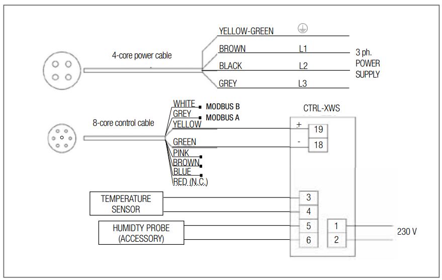
9.3 CTRL-XWS (accessory on request)
9.4 CTRL-XTHI (accessory on request)

9.5 CONTROL WITH EXTERNAL POTENTIOMETER (not supplied)

10 CLEANING
The unit (IP65) can be washed with water jets. In this case it is recommended to drill a hole under the plastic cover for water drainage.
11 TROUBLESHOOTING (Modbus)
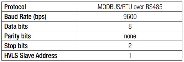
11.1 Connection parameters
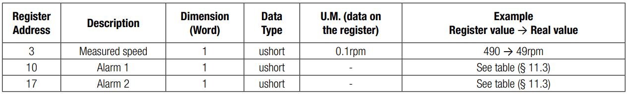
11.2 Modbus Registers – Input Register
These registers are READ-ONLY, and can be read using the function 04 READ INPUT REGISTERS.
11.3 Alarm codes/LED status/Troubleshooting

For additional information on HVLS Modbus control, contact the manufacturer/technical support.
12 DECLARATION OF CONFORMITY AND INCORPORATION

UE DECLARATION OF CONFORMITY
![]()
We herewith declare that the following range:
EHS series ceiling fans
BRAND: AERAULIQA
MODELS:
EHS360, EHS400, EHS500, EHS540
EHS600, EHS730, EHS730plus on the basis of its design and construction as partly completed machines brought onto the market, is designed in compliance within relevant health and safety requirements of the following Directives:
2014/35/UE – Low Voltage Directive (LVD)
2014/30/UE – Electromagnetic Compatibility (EMC)
2009/125/EC – Energy Related Products (ErP)
in the event that alterations are made to the machinery without prior consent with the manufacturer, this declaration becomes invalid.
This declaration is issued under the sole responsibility of the manufacturer.
UE DECLARATION OF INCORPORATION
In accordance with the Machinery Directive 2006/42/EC.
We herewith declare that the following range:
EHS series ceiling fans
BRAND: AERAULIQA MODELS: EHS360, EHS400, EHS500, EHS540 EHS600, EHS730, EHS730plus
on the basis of its design and construction of partly completed machines, is designed in compliance with the Essential Health and Safety Requirements (EHSRs) of ANNEX l, sections 1.1.2 (Safety integration), 1.1.5 (Handling), 1.4.1 (Protective devices), 1.5.1 (Electricity) of EC Machinery Directive 2006/42/EC.
The machinery is incomplete and must not be put into service until such time as the machinery which is partly complete is to be incorporated and has been assessed and declared in conformity with the provisions of the Machinery Directive 2006/42/EC.
We undertake to transmit, upon reasoned request by appropriate national authorities, relevant information on the partly completed machinery identified above.
Montichiari, 01/03/2025
![]()
During installation, it is recommended to write the serial number of the unit in this manual and keep it safe for maintenance service.
SERIAL NUMBER
![]()
Aerauliqa S.r.l. – via Mario Calderara 39/41, 25018 Montichiari (Bs)
C.F. e P.IVA/VAT 03369930981 – REA BS-528635 – Tel: +39 030 674681 – Fax: +39 030 6872149 – www.aerauliqa.it – www.aerauliqa.com – info@aerauliqa.it
Aerauliqa S.r.l. reserves the right to modify/make improvements to products and/or this instruction manual at any time and without prior notice.
Documents / Resources
 | aerauliqa EHS Range Ceiling High Volume Low Speed Fan [pdf] Instruction Manual 12, 22, EHS Range Ceiling High Volume Low Speed Fan, EHS, Range Ceiling High Volume Low Speed Fan, Ceiling High Volume Low Speed Fan, High Volume Low Speed Fan, Volume Low Speed Fan, Low Speed Fan, Speed Fan |