1. Introduction
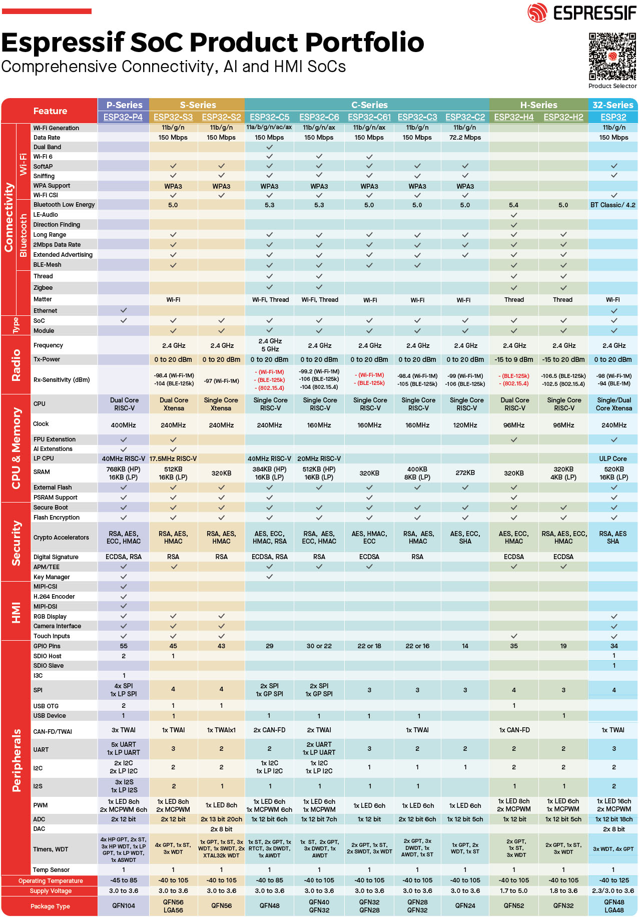
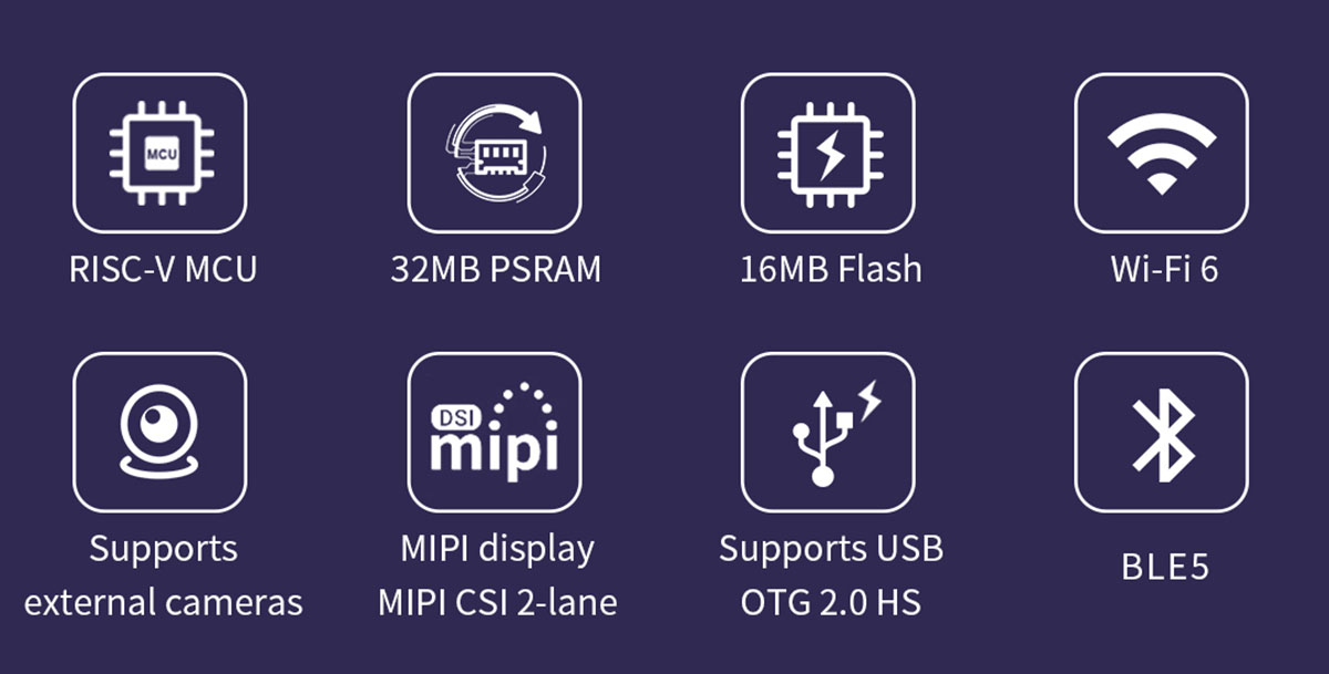
This document provides comprehensive instructions for the ESP32-P4 4.3-inch 480*800 IPS HMI LCD Module. This display development board integrates ESP32-P4 and ESP32-C6 chips, offering Wi-Fi 6 and Bluetooth 5 wireless connectivity. It is designed for a wide range of human-machine interface (HMI) applications, supporting various interfaces including MIPI-CSI (with an integrated image signal processor ISP), MIPI-DSI, SPI, I2S, I2C, LED PWM, MCPWM, RMT, ADC, UART, and TWAI. It also supports USB OTG 2.0 HS.
The ESP32-P4 features a 360MHz dual-core RISC-V processor and up to 32MB of PSRAM. It includes peripherals like USB 2.0, MIPI-CSI/DSI, and H.264 encoding, making it suitable for low-cost, high-performance, and low-power multimedia development. The ESP32-P4 also integrates a digital signature peripheral and a dedicated key management unit for data and operational security.

2. Key Features
- High-performance MCU with RISC-V 32-bit dual-core and single-core processors.
- 128KB HP ROM, 16KB LP ROM, 768KB HP L2MEM, 32KB LP SRAM, 8KB TCM.
- Robust image and audio processing capabilities, including JPEG codec, pixel processing accelerator (PPA), image signal processor (ISP), and H.264 video encoder.
- 32MB PSRAM stacked within the chip package, with 16MB Nor Flash integrated into the module.
- On-board interfaces for MIPI-CSI, MIPI-DSI, USB 2.0 OTG, and SDIO 3.0 SD common peripheral interfaces.
- Security mechanisms: Secure boot, Flash encryption, hardware encryption accelerator, and hardware random random number generator. Supports hardware access protection, enabling access permission management (APM) and permission separation.
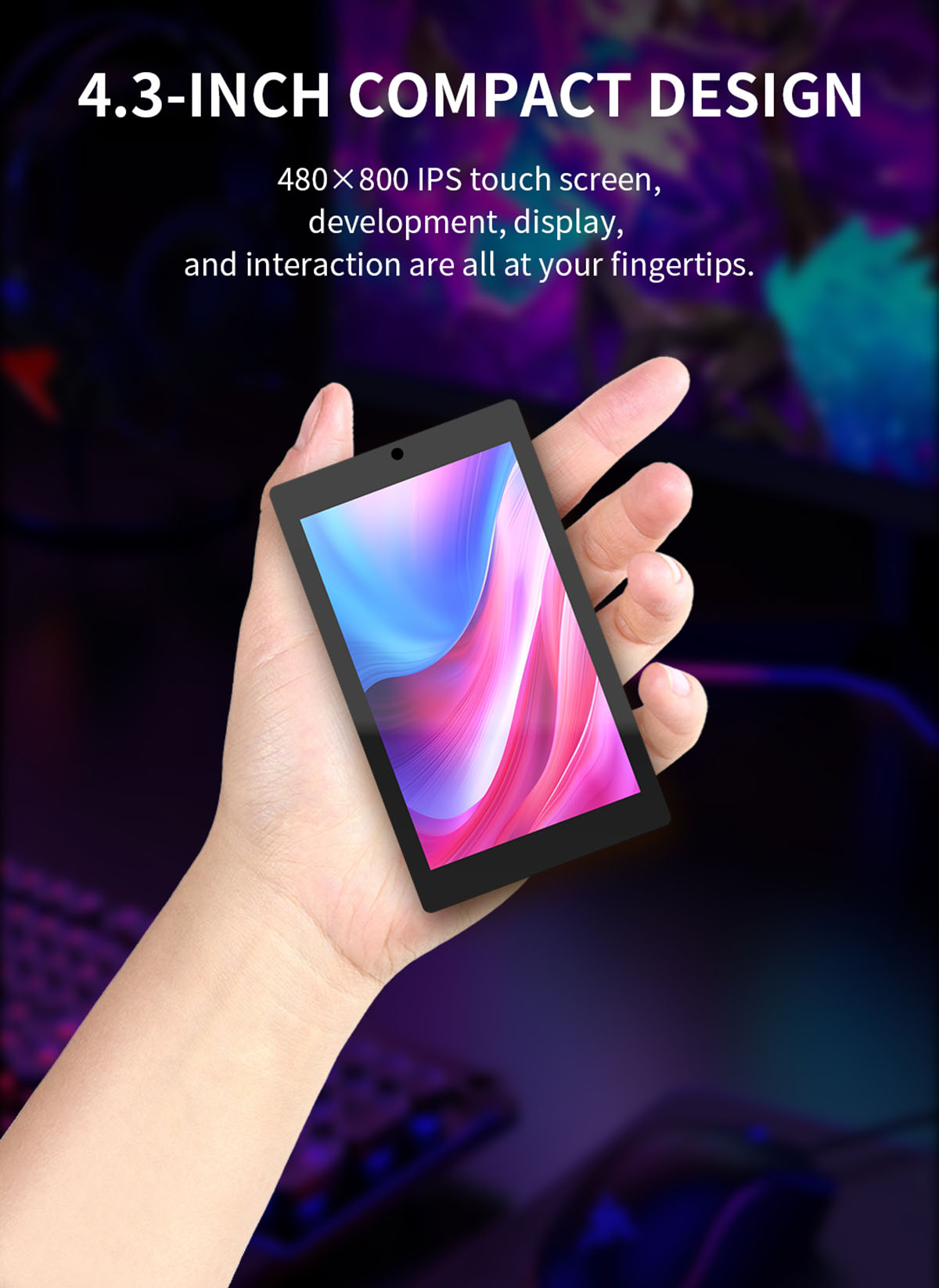
- 4.3-inch color screen supporting 16.7M colors.
- 480x800 resolution.
- Optional camera and enclosure.
- Pre-programmed with a sample program for immediate use.
- TF card slot for expanded storage.
- Arduino library functions and sample programs for rapid secondary development.
- Lithium battery charging and discharging circuit with overcharging and discharging protection.
- Support for one-click program download.
- Additional IOs available for custom use.
- Military-grade process standards for long-term stable operation.
3. Specifications
| Item | Description |
|---|---|
| Brand Name | SURENOO |
| Model Number | JC4880P443C |
| Type | IPS TFT |
| Display Color | 16.7M Color |
| LCD Controller | ST7701S |
| Resolution | 480*800 (Pixel) |
| Module Size | 66.80*114.40 (mm) |
| Effective Display Area | 56.16*93.60 (mm) |
| View | IPS Full Angle |
| Operating Temperature | -20℃~70℃ |
| Storage Temperature | -30℃~80℃ |
| Operating Voltage | 5.0V |
| Power Consumption | About 360MA |
| High-concerned chemical | None |
| Display Mode | NC |
| is_customized | Yes |
| Interface | ESP32-P4 Display |

4. Setup and Connections
The JC4880P443 module is designed for flexible integration into various projects. It features a dual-chip architecture with ESP32-P4 and ESP32-C6 for powerful processing and connectivity.
4.1 Core Board Overview

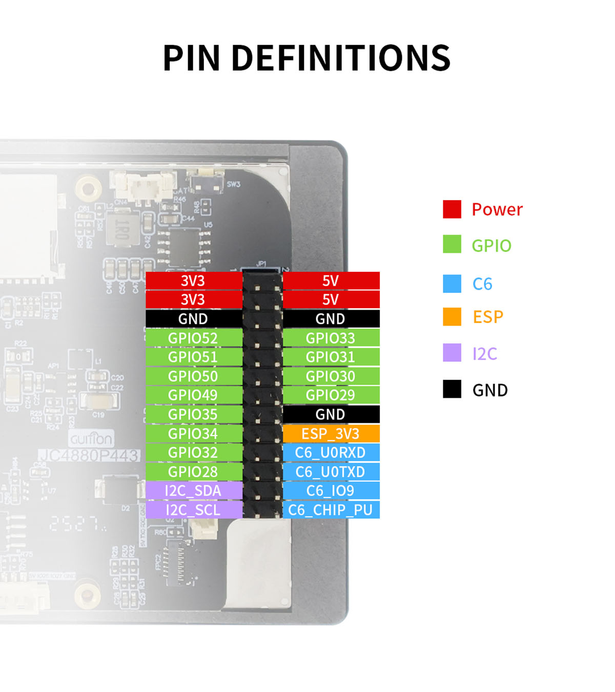
4.2 Pin Definitions
Understanding the pinout is crucial for connecting the module to external components and development boards. The module provides various power, GPIO, and communication pins.
4.3 Interface Connections
The module offers a variety of interfaces for expansion and connectivity:
- Microphone: For audio input.
- MX 1.25 2P Speaker Interface: For connecting an external speaker (speaker not included in basic package).
- MX 1.25 2P Lithium Battery Interface: For power supply from a lithium battery.
- Full-Speed Type-C: USB Type-C port for data transfer and power.
- High-Speed Type-C: Another USB Type-C port, likely for higher data rates or specific functions.
- 2*13 2.54 Pin Header: General purpose input/output pins for custom connections.
- MX 1.25 4P UART0: UART (Universal Asynchronous Receiver/Transmitter) interface for serial communication.
- Camera Interface: For connecting an external camera (camera not included in basic package).
- MX 1.25 4P UART Interface: Another UART interface.
- MX 1.25 4P 485 Interface: RS485 interface for industrial communication.
- HS 1.0 2P I2C Interface: I2C (Inter-Integrated Circuit) interface for communication with peripherals.
- ESP32P4+ESP32-C6 Core Board: The integrated main processing unit.
Note: The basic version of the module does NOT include a camera or enclosure. The enhanced version includes both.
5. Operating Instructions
The ESP32-P4 HMI LCD Module is designed for interactive applications. Below are common operational aspects:
5.1 Touch Screen Interaction
The module features a capacitive touch panel, allowing for intuitive interaction with on-screen elements. You can tap, swipe, and use multi-touch gestures depending on the application's programming.
5.2 Connectivity (Wi-Fi & Bluetooth)
With the integrated ESP32-C6 chip, the module supports 2.4GHz Wi-Fi 6 and Bluetooth 5/BLE. This enables stable connections and efficient data transmission for network-dependent applications or communication with other Bluetooth devices.
5.3 Multimedia Playback
The module supports audio and video playback, which can be enhanced by connecting external speakers via the dedicated speaker interface. The powerful dual-core processor and hardware-accelerated H.264 & JPEG processing ensure smooth multimedia experiences.
5.4 Demonstration Video
Watch the following video for a demonstration of the module's capabilities, including touch screen functionality, calculator, music playback, video playback, Wi-Fi connection, volume and brightness control, mini-games, and built-in camera (if equipped).
6. Development and Programming
The module supports development using popular platforms such as Arduino IDE, ESP IDE, Micropython, and LVGL. While default firmware source code is not provided, basic LVGL display and touch examples are available to help you get started.
6.1 Datasheet and Resources
For detailed technical information and development resources, please refer to the official datasheet:
- Datasheet Link: http://pan.jczn1688.com/s/mo3t4j
7. Maintenance
- Keep the module in a dry environment and avoid exposure to moisture or extreme temperatures.
- Handle the module with care to prevent physical damage to the screen or components.
- Use a soft, lint-free cloth to clean the screen. Avoid abrasive cleaners or solvents.
- Ensure proper ventilation when the module is in operation to prevent overheating.
- When not in use for extended periods, store the module in an anti-static bag.
8. Troubleshooting
- No Display/Blank Screen:
- Check power connections and ensure the module is receiving the correct 5.0V operating voltage. Verify that the display cable is securely connected. If using custom firmware, ensure the display initialization code is correct.
- Touch Screen Unresponsive:
- Ensure the touch panel FPC cable is properly connected. If using custom firmware, verify the touch driver and calibration settings. Restart the module.
- Wi-Fi/Bluetooth Connectivity Issues:
- Check antenna connections (if external). Verify Wi-Fi credentials and network availability. Ensure Bluetooth is enabled and devices are in pairing mode. Update ESP32-C6 firmware if necessary.
- Module Not Powering On:
- Confirm the power supply is adequate and correctly connected. If using a lithium battery, check its charge level and the battery interface connection.
9. User Tips
- For optimal performance in development, ensure your development environment (Arduino IDE, ESP IDE) is updated to the latest version.
- When experimenting with external components like cameras or speakers, always double-check pin assignments and voltage requirements to avoid damage.
- Utilize the provided LVGL examples as a starting point for building custom graphical user interfaces.
- Consider using a dedicated power supply for stability during development, especially when integrating multiple peripherals.
10. Support and Resources
For further assistance, technical documentation, and community support, please refer to the following resources:
- Official Website: https://www.surenoo.com
- Datasheet Link: http://pan.jczn1688.com/s/mo3t4j
Shenzhen Surenoo Technology Co., Ltd. is a professional display solution supplier dedicated to providing high-quality products and technical support.