![]() Model GF Digital Glycol
Model GF Digital Glycol
Feeder with MegaTron XS
Controller Installation
Maintenance Repair Manual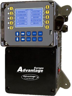
GF Digital Glycol Feeder with MegaTron XS Controller
Advantage Controls
4700 Harold-Abitz Dr.
Muskogee, OK 74403
Phone: 800-743-7431
Fax: 888-686-6212
www.advantagecontrols.com
Introduction
The Advantage Controls Glycol Feed Systems are design to regulate pressure in closed loop Hydronic Heating and Cooling applications.
The Advantage Controls XS Series Glycol Feeders are our advanced design microprocessor based controller with communication options previously unavailable with earlier models.
Standard XS Series Glycol Feeders are built to UL 508 industrial standards and is tested and certified by ETL. With standard outputs of: (2) dry contact relays (one for alarms and our for pump on), (1) timer for agitator control, 20 key data inlay, large multi-line display, audible alarm, motor starter / high amp relay, menu driven program, manual off auto function on all outputs and 4-20mA outputs.
Advantage Controls Glycol Feeders are stand alone pre-wired, pre-plumbed systems designed for ease of installation. Our systems are mounted on a powder coated steel frame with anchor points.
Advantage Controls model designation allows for a wide variety of configurations, operation and function of each Glycol Feed Systems and is dependent on your specific model number. Please check your model number against the selection guide for better understanding of your system.
Please read this instruction manual to become familiar with your system.
Model Numbering and General Specifications
BUILD A MODEL 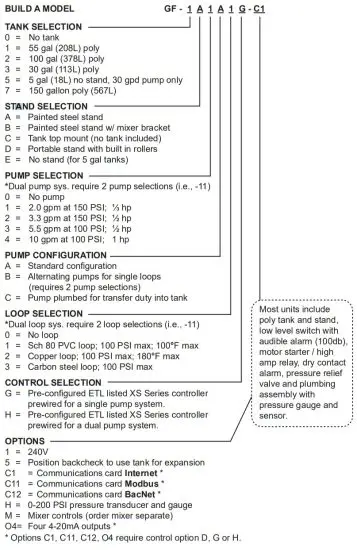
Specifications
Electrical
- Input 120 VAC, 60 Hz
- Alarm Dry Contact
- Motor: 1/3 HP Pump: 2 GPM
Plumbing
- Standard Schedule 80 PVC
- Optional Copper or Black Iron
Enclosure
Heavy Duty NEMA 4X style, high impact thermoplastic with padlockable gasketed Lexan viewing door
Pressure Gauge 0-100 psi (0-6.9 bar)
Dimensions
See measurements on page 7.
Shipping Weight
160 lbs (77.57 kg) approx.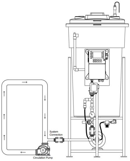
Base Functions
MegaTronXS units have several base system control functions and unit optional features. Your unit may be supplied with one or more of the features described in this manual. To determine what features apply to your unit check the model number label located on the controller enclosure.
Base System Control Functions
(1) Timer selectable (4) mA Inputs
Whole Unit Optional Features
A – Conduit Connections
C1 – Communications card Internet
C11 – Communications card Modbus
C12 – Communications card BacNet
M – Mixer controls
O4 – Four 4-20 mA outputs
Notice: Your unit may not have all features and functions described in this manual. This list represents our most popular options, additional option codes are available.
Installation
Electrical Wiring
The MegaTron XS series digital glycol feeder controller has an internal regulated power supply that will operate in the range of approximately 90 to 250 VAC at 47 to 63 Hz on the incoming wiring. Output relay(s) are protected with a replaceable fuse. Each relay’s output voltage will equal incoming line voltage. The Standard prewired units are supplied with a 8 foot, 16 AWG, 3 wire grounded, 120 VAC USA power cord for incoming power.
NOTE: Liquid tight fittings and labeled signal lead cables are provided for all signal (low voltage) connections, low drum level and pressure transducer.
![]() WARNINGS:
WARNINGS:
- The controller should be connected to its own isolated circuit breaker, and for best results, the ground should be a true earth ground, not shared. Wiring must be done according to all applicable local codes.
- Power (line voltage) must be disconnected while making any connections. If power is supplied to the unit, line voltage will be present on the relay cards.
- Low voltage signal wires (transducer, level, alarm, etc.) should never be run in conduit with high voltage wires.
Mounting Instructions
Select a mounting location that provides the operator easy access to the unit and a clear view of the controller.
The location should be convenient to grounded electrical connections and system plumbing connections.
Mount the glycol feeder stand to a level concrete pad using the ½” mounting holes in the base of the stand.
Concrete pad construction and anchoring bolts must comply with local building codes. The required sample line plumbing should be connected to the return header of the Hydronic system![]() WARNING:
WARNING:
Avoid locations that expose the controller to direct sunlight, vapors, vibration, liquid spills or extreme temperatures; less than 0°F (-17.8°C) or greater than 120°F (50°C).
EMI(electromagnetic interference) from radio transmissions and electric motors can also cause damage or interference and should be avoided.
4-20mA Output Card Wiring
A. Isolated Configuration
For isolated 4-20mA outputs, an external power source for the loop must be supplied. JP4 and JP5 on the board must be jumpered for isolated, with an external power source supplied to the external VDC input. The external power source must not exceed 24 volts DC.
B. Non-isolated Configuration
For non-isolated 4-20mA outputs, the controller will supply the power for the loop. JP4 and JP5 must be jumpered for non-isolated, and no connections are made to the external VDC points.
NOTE: The power for the mA output loop is always provided by the controller with either isolated or nonisolated configuration.
4-20mA Input Card Wiring
The 4-20mA input card requires that the external device sending the 4-20mA input signal(s) supply the power for the loop. The external power source must not exceed 24 volts DC.
NOTE: Older green versions of the 4 input cards supply +12 VDC and ground on the voltage terminals, and newer blue versions supply +12 and -12 VDC instead of ground on the “G” positions when configured for non-isolated voltage (the standard configuration).
NOTE: Units with only mA outputs may be provided with a card that has the four outputs at the bottom of the card or the top of the card, depending on version used.
Typical Installation and Measurements
 GLYCOL STAND FOOT PRINT
GLYCOL FEEDER STAND FOOT PRINT
1/4” bolt hole drilled 3/4” from outside edge
Note: This is for mounting holes only. Controller will extend beyond this depth.
| A | B | C | D | E | |
| 30 gal 113.5L | 23 ¾” 60.3 cm | 51” 129.5 cm | 27 ½” 69.8 cm | 25 ½” 64.7 cm | 30 ½” 77.4 cm |
| 55 gal 208.1L | 27 ½” 69.8 cm | 65” 165.1 cm | 27 ½” 69.8 cm | 25 ½” 64.7 cm | 32” 81.2 cm |
| 100 gal 378.5L | 31 ¼” 79.3 cm | 66” 167.6 cm | 37” 93.9 cm | 35” 88.9 cm | 38” 96.5 cm |
Glycol Feeder Start-Up Procedure
Complete all installation steps before beginning this procedure. Ensure that all controlled devices (pumps, solenoid valves, etc.) are operational and connected to the controller. \![]() WARNINGS:
WARNINGS:
Before applying power to the controller, remove the fuse(s) from the fuse holder(s) located on the high amp relay extension. There will be two (2) fuses on duel pump system. Reasoning behind this is, factory settings may not agree with your system and this gives time for you to set your parameters before applying power to the pump or pumps.
- Before filling tank, be sure that the tank and the filter bowl are free of packing material and or construction debris.
- Check plumbing as it may have become loose from vibrations during shipping.
- Fill Tank
- Open the valve closest to the drain port of the plumbing assembly by turning the handle clockwise.
Water will pass through the sample stream assembly. - Ensure that the system pressure does not exceed 100 psi.
- Check all fittings of the plumbing assembly for leaks. If there are no leaks verify that the pressure gauge agrees with system pressure. This value may vary do to connection to Hydronic systems placement.
- Apply power to your system to check configuration of the pressure setpoint.
- Once you are familiar with the controller from either reading the instruction manual or trial and error, proceed with setting perimeters that are correct for your hydronic system.
- Power off the controller, insert the fuse(s) into the fuse holder(s) located on the high amp relay extension.
- Power ON the control to verify proper operation.
Pressure Relief Configuration Procedure
- Pressure relief values are set at 75 psi by default from the factory.
- To increase the psi, spin the valve clockwise.
- To decrease the psi, spin the valve counter clockwise.
- To test, close drain port valve slowly to raise system pressure to the relief level.
- Open drain port valve to relieve system pressure and conclude test.
Alarm Buzzer Disable and Enable Procedure
- Press the 0 key at the home screen to enter into the relay status screen.
- Press the 2 key twice after entering into the relay status screen to disable the alarm buzzer.
- Press the 2 key once more to set the relay back to the normally pressure automated state.
- Press the 2 key once more to force the alarm buzzer relay ON.
Pressure Setpoint Configuration Procedure
If these are improperly set by entering an A/D value for the settings while the input is not seeing the correct signal a signal generator will be required to reset the calibration.
Step 1:
Push the HOME button to leave Calibration and go back to the HOME menu screen. From here push SETPOINTS (Button 1) to go to the next screen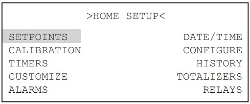
Step 2:
This is the Setpoints Setup Screen. From here push mA IN (Button 7) to go to the next screen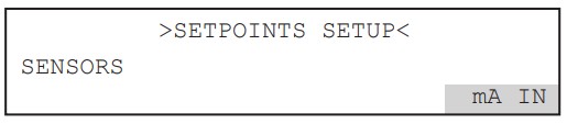
Step 3:
This is the mA Inputs Screen. From here push INPUT 1(Button 1) to go to the next screen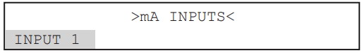
Step 4:
This is the mA Input 1 Setpoint Review Screen. From here push SETPOINTS (Button 5) to go to the next screen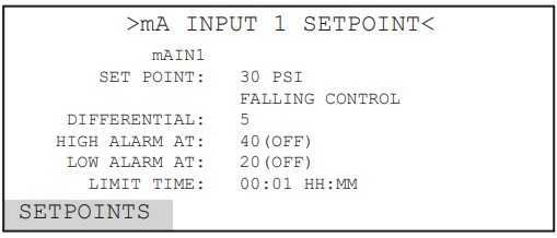
Step 5:
This is the mA Input 1 Setpoint Change Screen.
From here you can set SET POINT (Button 1), DIFFERENTIAL (Button 2), HIGH ALARM (Button 3), LOW ALARM (Button 4) and LIMIT TIME (Button 5). Press the desired button to go to the next screen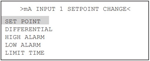
Step 6:
Set the value of SET POINT by using the number keys. Use the left arrow to set the reaction direction of the set point between RISING or FALLING. Then press ENTER to confirm and go to the previous screen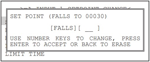
Step 7:
Set the value of DIFFERENTIAL by using the number keys. Then press ENTER to confirm and go to the previous screen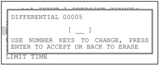
Step 8:
Set the HIGH ALARM settings for VALUE (the reading that will give a High Alarm) and NOTIFICATION. Press ENTER to confirm and go to the previous page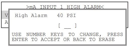
Step 9:
Set the value of the ALARM NOTIFY by using the arrow keys. Then press ENTER to confirm and go to the previous screen.
Note: Display – will appear on controller display only, Remote – appears through email if controller is online, or both Dis/Remote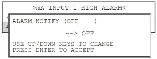
Step 10:
Repeat Steps 19 and 20 for the LOW ALARM.
Press BACK to return the mA Input 1 Set Points
Step 11:
Set the value of LIMIT TIME by using the number keys. Then press ENTER to confirm and go to the previous screen. The Limit Time and the Alarm Notification will need to be set. Press HOME when finished to return to the HOME menu Note: If the Limit Time is met a relay activated by the 4-20mA input will be forced off until the Set Point has been satisfied and reset.
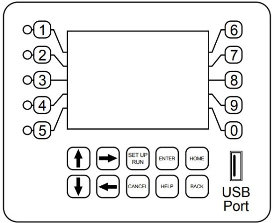
Front Panel Description

NUMBER Keys- Used to enter new values in the SET UP mode and to access desired sub menus.
UP/DOWN – Used to cycle through text options to find desired setting.
LEFT/RIGHT – Used to cycle through text or setting options to find desired setting.
SET UP/RUN – System initializes into RUN mode. Press this key to put the controller in SET UP Mode and see HOME menu page.
ENTER – Used to log a changed value into program.
HOME – Used to go back to the HOME menu page.
CANCEL – Used to cancel a pop-up screen if no change is desired.
HELP – Used to access help screens.
BACK – Used to go back to last menu screen viewed or clear values keyed in that are not wanted.
The bottom right box in the RUN screen mode is a hot key that will take you directly to a particular menu screen. The default is the RELAY status menu but this can be changed by navigating to the desired screen and pressing the HELP button. Follow the on-screen instructions to set the new hot key location.
System Operation Overview
Operation
MegaTronXS controllers have two modes of operation, RUN and SET-UP.
RUN – This mode is for normal operation. In the RUN mode the display will show each system’s parameters.
If an alarm is present, the ALARM box will flash how many alarms are activated. No settings may be entered or changed in the RUN mode. Readings are updated every 6 seconds on the screen while in the RUN mode.
SET-UP – This mode is used to make adjustments to settings and readings on the controller. To access the SET UP mode from the RUN screen, press the SETUP/RUN key.
To access the menus press the Set Up / Run key on the front panel. This takes you to the Home menu.
MegaTronXS controller’s menus are easily navigated by pressing the associated number key next to a menu box on the screen. Once you have stepped through the sub menus to reach a point at which a value or selection is made a Pop-up window will appear prompting you to enter a desired value or selection.
NOTE: When entering new numeric values, enter all available digits (characters).
1. Home Menu
 From the HOME menu select the desired menu.
The menu name explains what parameters can be programmed in the menu.
SET POINTS – Setting control set points for pressure.
CALIBRATION – Calibrating pressure.
TIMERS – Menu for selecting type and settings for all present feed timers.
CUSTOMIZE – Giving the controller, each system and all relays a user defined name.
ALARMS – View current alarms.
DAY/TIME – Menu for setting date and time.
CONFIGURE – Menus for configuring passwords, relay activations, setting history interval, flow switch, contrast, temperature scale.
HISTORY – Allows for view history on board in a graph form.
WATER METER – Menu for configuring water meter totalizing.
RELAYS – Menu for resetting accumulated “ON” times and manual relay activation.
2. Set Points
The same basic format is used for defining each available analog probe input’s control parameters..  SET POINTS – For setting the relay set points for the available analog probe readings such as 4-20 mA inputs for pressure.
NOTE: In the Setpoints pop-up screen the direction (Rising or Falling) of the setpoint can also be set for mA input sensors. If the setpoint is configured for ‘Rising’ the pump output relay will activate when the PSI reading exceeds the setpoint. The pump output relay will remain activated until the PSI reading falls below the setpoint by the amount of the differential. If the setpoint is configured for ‘Falling’ the pump output relay will activate when the PSI reading falls below the setpoint. The pump output relay will remain activated until the PSI reading rises above the setpoint by the amount of the differential.
2.1 Aux Inputs (Digital Inputs)
Auxiliary inputs are the digital inputs for the low drum level (wand) alarm and any other optional digital inputs.
From these menus the user can set if they want each of the alarms Displayed, Remote Notification, both or none. 
Note: Digital inputs can have the direction selected between OPEN or CLOSED as the alarm polarity. If set for CLOSED the input will be in alarm when it sees a closed contact.
For typical Glycol Feeder applications the low drum level (wand) sensor is assigned to Digital Input 1 and is set to CLOSED
2.2 4-20mA Out
Units with a 4-20mA output option will have a menu for setting up the 4-20mA output. The 4mA and 20mA values can be defined by giving the output proportioning capability. i.e. 4mA = 0.0 PSI and 20mA = 100.0 PSI.
SIGNAL SOURCE – Select which probe reading the mA will use as its reading source.
4 mA VALUE – What the 4mA signal equals 20mA VALUE – What the 20mA signal equals on the assigned signal sources scale.
2.3 4-20mA Input
SET POINT – What reading turns the relay on
DIFFERENTIAL – Amount reading changes by before the relay is turned off (min. 5 PSI diff. recommended).
HIGH ALARM – What reading generates a High alarm notification.
LOW ALARM – What reading generates a Low alarm notification.
3. Calibration
Calibration is for adjusting the displayed value of a probes reading to match your tester or known solution.
Pick the system or mA input first. From a particular system pick the probe to calibrate.
All MegaTronXS controllers are factory calibrated. All units are shipped with the date preset, and the clock set to your current time. These readings and settings should be verified for accuracy, and adjusted as per the instructions listed below.
3.1 4-20mA Output Calibration 4-20mA outputs can be calibrated to insure that the output generated by the controller and received by the external device match. With a volt meter connected across the out and return wires (see page 24) of the 4-20mA output channel to be calibrated go into the output’s Low or High calibration.
 The number displayed in the Calibration dialog box can range from 0-4095 with 800 equal to 0 mA output and 4030 equal to 20 mA. This number range of 0-4095 is the raw digital to analog (D/A) values and is strictly used for a reference. The D / A numbers you get will vary based on your installation conditions.
 While in the High or Low calibration pop-up screen use the up and down arrows to change the output value being read with the volt meter. Adjust the High value for the 20 mA reading and the Low value for the 4 mA value.
3.2 4-20mA Input Calibration
4-20mA inputs can be calibrated to insure that the input seen by the controller from the external device match.
It also allows for setting the 4-20mA input into a number range that relates to the value being read.
Firmware version KA.16.03 and up have logic that suspends any control logic if the mA received is 50% below the stored 4mA value. A # will be placed in the RUN screen for any mA value in this invalid state. The 20mA and 4mA values are where the controller’s raw analog to digital value is adjusted to match a 20mA (full scale) and 4mA (bottom of scale) signal from the external device inputting the 4-20mA input. The external device must be connected to the controller and showing either full scale or bottom of scale when calibrating each. The number shown along with either the 20mA or 4mA while calibrating is the raw A/D value and is only a reference. A 20mA input should be around 5500 and 4mA around 1100. If the A/D numbers are not in this range check input device.
The MAX and LOW calibration inputs are for telling the controller what to display for a 20mA input and a 4mA input. For example if the input is a drum level sensor monitoring a 55 gallon drum the value for MAX should be 55 and LOW should be 0. The controller then displays a number automatically ranging between 55 and 0 based on the input value. The units of measure (gallons for example) is set in the Customize menu from the Home page.
OFFSET – Changes the current displayed value of the 4-20mA input reading to allow for a manual 1pt calibration of the displayed value.
FACTORY DEFAULT – If the 20mA or 4mA calibration has been incorrectly set (not at 4 or 20) this will reset the settings back to a factory value for 4 and 20.
4. Timer
Timers aren’t a typical need in glycol feeder applications but available for custom configuration. A unit may have up to (1) timer standard for each system on a controller. All timers are associated with their system, so for a % of post bleed timer looks at the bleed of that system. TIMER – Select the type (28-day, pulse, limit, percent or percent of post blowdown) as well as the run times of each timer available per system.
4.1 Timer Type Selection
A pop-up screen lets you scroll through the various timer types available. Pulse – A water meter activated timer
Recycle – A continuous recycle timer with ON and OFF settings.
28-Day – A biocide or event timer.
4.2 Timer Set Up
Each timer type selected will have its own unique Set Up sub menu with additional selections specific to the type of timer selected. The page displayed before entering the Set Up menu of a timer provides an overall review of the timers current settings.
4.3 Recycle Timer
ON CYCLE – The amount of the defined time that the timer is to be on.
OFF CYCLE – The amount of time that the cycle is going to be on.
ON/OFF TIMER – This is the displayed count down of time for the cycle the timer is in.
4.4 28-Day Timer
Each 28-day timer has Program 1-4 for programming the various feed times. While the programming steps for four programs are the same each can have it’s own independent settings.
WEEKS – The week(s) that the timer is to feed.
DAYS – The day(s) that the timer is to feed.
START – The time of day for the timer to start.
RUN – How long the timer is to run.
FEED LOCK – Which other system timer to lockout during this timer’s run time.
FLOW LOCK – If the system has a flow switch you can ignore it for this timer.
5. Customize
This menu allows the user to define the on-screen name of the unit plus the name of each system and relay.
The user can also setup the Notepad for each system and 4-20mA Input’s name and unit of measurement.
RUN SCREEN – Allows the user to select what will be shown on the screen while the controller is in the RUN mode. Like displaying temperature readings, water meter totals for a particular system or the conductivity units of measure.
NOTE: When entering values for custom names use the numerical keys for numbers and the up / down arrows to scroll through all the characters of a key board. Press the right arrow to advance the curser after setting a desired value. Press the Help button to place the last entered character into the new cursor space to speed up the process. The Help button will also jump advance through the characters.
5.1 Notepad
The Notepad function allows the user to set up a customized manually entered data field for each system with ten notepad items. The NOTEPAD is ideal for setting up and storing into the controller’s history the items typically tested for reporting a service call. The Notepad items come with no names but when an individual note is selected a menu for setting it appears. 
NAME – Pick from a list of defined names or customize your own.
NUMBER – Set the number range.
UNITS – Set the units of measurement.
ALARMS – Set Hi/Low alarm points and how frequently a new value is expected to be manually enter via the History menu.
5.2 mA Inputs
 NAME – Name the input.
UNITS – Set the units of measurement.
NUMBER – Set the number range.
5.4 Run Screen
This lets you customize various aspects of the RUN screen. MAIN SCREEN – Customize what is displayed on the RUN screen.
SCREENS SHOWN – Pick if the mA input & Aux Flow screens are scrolled.
CYCLE TIME – The amount of time between screen scrolls.
COND UNITS – Select the units of measure to be displayed with the conductivity reading.
6. Alarms ALARMS – Shows any current alarms.
7. Date and Time Set Up DATE AND TIME – For setting the date, time, day and week on the controller.
8. Configure
Provides access to menus to set-up passwords, relay activation, temp scale, display contrast, flow switch, inputs, history time stamps, factory set-up and system information. CONTRAST – This screen allows for adjusting the display contrast.
FLOW SW – Defines a flow switch to be open or closed with flow.
FACTORY – A factory only menu
TEMP SCALE – Set Celsius or Fahrenheit
HISTORY – Sets the history time stamp interval.
SYS INFO – Tells unit software specifics.
8.1 Password

ADMIN PASSWORD – The administrator password gives access to all menus except factory set up.
USER PASSWORD – The user password allows the user to access HOME menus that are made available in USER SET UP.
8.2 Relays (factory pre-configured) CONFIGURE RELAYS – This menu lets you choose a Main Action or function (timer 1, conductivity, alarms etc…) to activates a relay.
A pop-up screen appears with a list of all available activation functions to arrow through.
Additional relay logic is available with up to 3 additional Activators and up to 4 Disablers allowing multiple functions to activate the same relay and multiple functions to prevent the relay from coming on. There is also a Daily Max amount of time that a relay can be on. If a relay is on for the max amount it does not let the relay come on anymore that day. (A 24 hour clock is used for the day with midnight being the start of the day). The Delay setting is the amount of time a control function must come on before the relay will react and activate. This is to prevent a relay from chattering on/off if a reading is bouncing around the set point or alarm.
8.3 History
This menu is used to set the history “time stamp” interval, the water meter daily history starting hour and the alarm delay period.
INTERVAL – The amount of time between each history time stamp for probe readings.
W/M HOUR – The time of day that the daily water meter history cycle is to start.
ALARM DELAY – The amount of time an alarm has to be on before it is recognized as an alarm.
8.4 Flow Switch
This menu allows the user to select if a flow switch signal will represent a flowing condition when a “closed” or “open” signal is seen for each systems flow switch input. User can also select if timers can work always or only with flow.
8.5 Contrast
This menu is used to adjust the contrast of the display.
8.6 Temperature Scale
This menu is used to select the type of temperature scale to display.
8.7 Network (if applicable)
The Network menu is used when a controller is being remotely communicated with either a local network connection or over the internet on the Web Advantage server. NETWORK – This menu is used for setting up the remote WebAdvantage communications and is covered in a separate manual.
8.8 System Information
System information will identify the version of firmware installed in the controller along with the controller’s serial number.
9. History
The onboard history allows for viewing the history of the probe readings, relay activations, key-pad activity, calibrations, water meter hourly and daily logs and alarms for each system present. It is also where Notepad data is entered and reviewed. An initial overview page is displayed showing your current sample interval, the calculated number of days the unit can keep probe history for before losing the oldest. The number of sensor samples and relay/alarm events and Notepad entries currently stored is also displayed.
NOTE: The history can be reset by going to the configure menu and entering a different sample interval. After the new sample interval has been set the onboard history is reset.
9.1 Viewing History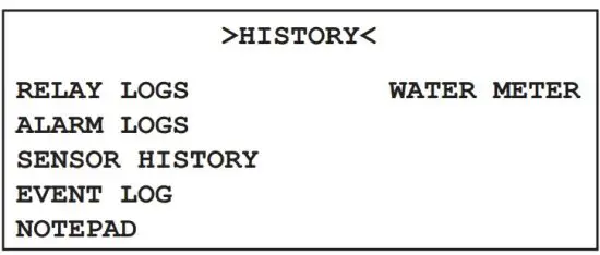 RELAY LOGS – Relay activations displayed in a log form. Arrow up to advance through the log.
ALARM LOG – Alarm activations in log form.
SENSOR HISTORY – For selecting the parameters and viewing of a given probe reading’s history in log or graph form.
EVENT LOG – Displays various activities.
9.2 Notepad Entries The Notepad section under History is where the user goes to enter new values for the customized notepad items. Each individual notepad item’s manually entered entries are stored in the units history and can be reviewed in log or graph form after 4 or more values have been entered.
10. Relays STATUS – Allows for viewing accumulated relay ON times, temporary forcing relays ON or OFF or seeing which relay is on.
RESET – Allows the accumulated run time of a particular relay to be reset to zero.
FORCE – Allows a relay to be manually forced ON for a single event from 0-99 minutes. When the event is over the relay goes back to it’s normal automatic control. In the STATUS view the accumulated ON time is shown along with the main activator, custom name and current status:
ON = Relay on by relay activators
OFF = Relay off by normal logic
OFF-T = Relay off for daily max
OFF-D = Relay off for relay disabler
ON-A = Relay activated by activator other than main action
H-ON = Relay manually forced on
H-OFF = Relay manually forced off
USB Functions
The XS is capable of transferring information using a FAT formatted USB drive. The XS has three
main functions that it can perform using the USB.
- Upgrade XS Firmware from USB Drive
- Save XS Log Data to USB Drive
- Clone User Settings between XS units.
Upgrade XS Firmware
To upgrade the firmware on your XS, copy the updated software version to use to a USB drive. The file name should be “firmware.bin” Plug the USB drive containing this file into the XS USB connector. The USB DRIVE DETECTED pop-up window will appear. Use the up and down arrows to choose the “Update Firmware” selection. Press ENTER. It may take a few minutes for the update process to complete. Do not remove power or the USB drive during program updates. Once the firmware update is completed, the XS will automatically reboot. Once the system reboots, the USB DRIVE DETECTED screen will re-appear.
Remove the USB Drive and this window will close.
Save XS Log Data to USB
History from an XS controller can be saved to a USB drive in one of two file formats (WebAdvantage or a generic Comma Separated). You can select what type will be transferred in the Configure menu under History there is a selection called Save Format. The WebAdvantage format is the default for then uploading history to WebAdvantage for cloud storage and graphing. Change to Comma Separated if using with Excel.
To transfer the contents of the XS history logs to the USB drive, plug a USB drive in to the XS USB port. The USB DRIVE DETECTED pop-up window will appear. Use the up and down arrows to choose the “History>USB” selection. Press ENTER. It may take a few minutes for the process to complete. Status will be displayed on the screen to show the percent completed of each log record type. Once the log is completely stored, the pop-up window will close. The USB drive will now contain a file named “LOG.TXT”.
Cloning an XS
The XS has the ability to copy the User Settings from one XS to another. This process is referred to as cloning. To clone your XS, insert the USB drive into the XS with settings you want to save for cloning. Once the USB DRIVE DETECTED pop-up window appears, use the up and down arrows to choose the “Config>USB” selection. Press ENTER. The User settings will be saved to the USB drive under the file name “CONFIG.BIN”. The pop-up window will close when the copy is completed.
Take the USB drive and plug it in to the XS that you would like to copy the User Settings to. When the USB DRIVE DETECTED window appears, use the up and down arrow keys to choose the “USB->Config” selection. Press ENTER. The User Data will be loaded in to the XS from the USB drive. Once the pop-up window closes, the cloning is completed.
![]() Warning:
Warning:
- Not all customized names are saved.
- USB drives must be FAT formatted to work correctly.
Troubleshooting & Maintenance
The Advantage Glycol Feeder is designed for many years of trouble-free operation. Should a problem occur, refer to the following to help identify the problem.
NO POWER TO CONTROLLER
- Disconnect plug from live receptacle.
- Remove keypad panel to access relay board in the back of the enclosure (see page 6).
- Locate green 3 position connector in bottom right corner of board and make sure it is securely plugged in with all three wires tightly screwed down in the connector.
- Locate logic ribbon cable on left side of relay board and make sure it is securely connected at both ends.
- Before replacing the panel, do a quick visual of all connections and wiring to ensure no other damage has occurred.
- Replace panel and secure.
- Plug in power cord and proceed with Start-up.
- If power issue was not corrected. Record Model /Serial Numbers and call customer service at 918-686-6211.
PUMP DOES NOT RUN WHEN RELAY INDICATOR IS ILLUMINATED
- Check fuse and that the fuse holder is secure.
- Check pump wiring.
- Check level of fluid / depth of level wand to make sure low level doesn’t have it forced off.
- Under the configuration menu, confirm that DigIN is set to Drum 1&2
- Disconnect level wand connection and short tips together in connector going back to controller (this is low voltage). Alarm should sound and pump stop when the input sees a closed contact.
• If Yes,inspect end of level wand for debris or damage,replace if needed.The float at bottom of the wand should have free movement, up and down.
• If No, inspect wire for damage. If no damage visible inspect internal wiring (see page 6). - If no resolution is found, record Serial / Model numbers and call customer service.
LOW LEVEL ALARM STAYS ON
- The low level input goes into alarm when there is a closed contact on the input. Disconnect level wand connection and the alarm should go off.
- If this turns off the alarm. Inspect the float to make sure it is moving freely.
- If the float is free moving there is a problem with the wand and it should be replaced.
- If disconnecting the connecter does not turn off alarm. Inspect internal wiring (see page 6).
- If no resolution record Model / Serial numbers and call customer service.
PUMPING PERFORMANCE INSUFFICIENT OR BLOWS FUSE
- Check if valves are fully open.
- Check/clean strainer. Prolonged exposure to debris in the glycol may damage pump.
- If pump has been run dry for a prolonged time, the pump may need to be replaced.
Advantage Controls has used different makes of glycol feed pumps but only offers the newer style rotary vane as a replacement for older models that used a gear pump. The newer pumps may require a new larger suction strainer assembly and tubing. Here are the models and required suction sizing based on the Pump selection code in the model number (see model numbering on page 3):
| Pump Code | Replacement | Suction Assembly |
| 1 | GFPUMP-1 | GF-1-SUCTION includes ½” strainer and 3/8” tubing |
| 2 | GFPUMP-2 | GF-2-SUCTION includes ½” strainer and ½” tubing |
| 3 | GFPUMP-3 | GF-2-SUCTION includes ½” strainer and ½” tubing |
| 4 | GFPUMP-4 | GF-4-SUCTION includes ¾” strainer and ¾” tubing |
Maintenance
Maintenance and care will depend upon the usage and environment in which the system is subjected to.
The following is the suggested regular maintenance required to keep the glycol feed system operating properly:
TANK AND PLUMBING
Periodically check the piping and tubing to insure proper discharge of the glycol solution. The strainer should be periodically checked for clogging and wear. The level wand should be removed and cleaned to prevent clogging.
FEED PUMP
Check for proper operation. If any pump/motor noises, leaks or changes in operation are detected, the pump should be removed and examined by a certified technician. Pump repairs can be difficult and should only be attempted by qualified personnel. Improper repairs or assembly can result in pump failure and voiding of the warranty. No lubrication is required.
PRESSURE RELIEF VALVE
Periodic checking and replacement of the adjustment seal is the only maintenance required.
Parts List
- Level wand for 30gl = ALL-S30; 55gl = ALL S42
- Tank lid for 30gl = LID-30-C1D; 55gl = LID-55-C1D
- Tank for 30gl = AGF-APCT-30; for 55gl = AGF-APCT-55
- Pressure relief valve = AGF-PRV
- Controller
- Isolation valve = BV-3/4 for PVC; GV-3/4 for copper
- Back check = CKV-3/4PP for PVC; CKV-3/4B for copper
- Pressure guage = AGF-PG
- Pressure transducer = AGF-PTD
- Suction shut-off and strainer asssembly = AGF-SUCTION
- Pump = See model number too identify desired replacement pump output.
1 = GFPUMP-1 for 2 gpm @ 150 psi
2 = GFPUMP-2 for 3.3 gpm @ 150 psi
3 = GFPUMP-3 for 5.5 gpm @ 100 psi
4 = GFPUMP-4 for 10 gpm @ 100 psi
Note: This list covers most of our popular models.
For models not covered, consult factory.

Pressure Relief Valve Specifications
- Sizes 1/2” and 3/4”
- Inlet (bottom) is male threaded, NPT
- Outlet (side) is female threaded, NPT.
- Buna-N disc on machined body seat.

| Gallons per Minute at Pressure | |||||
| Model | 50 psi | 100 psi | 150 psi | 200 psi | 250 psi |
| GFPUMP-1 | 2.1 | 2.05 | 2 | 1.95 | 0 |
| GFPUMP-2 | 3.6 | 3.4 | 3.2 | 3.1 | 0 |
| GFPUMP-3 | 5.51 | 5.5 | 5.41 | 0 | 0 |
| GFPUMP-4 | 10.2 | 10.1 | 10 | 9.5 | 9.2 |
Wiring Diagrams

Manufacturer’s Product Warranty
Advantage Controls warrants units of its manufacture to be free of defects in material or workmanship. Liability under this policy extends for 12 months from date of installation for all aspects of the glycol feeder with the controller only covered for an additional 12 months. Liability is limited to repair or replacement of any failed equipment or part proven defective in material or workmanship upon manufacturer’s examination. Removal and installation costs are not included under this warranty. Manufacturer’s liability shall never exceed the selling price of equipment or part in question. Advantage disclaims all liability for damage caused by its products by improper installation, maintenance, use or attempts to operate products beyond their intended functionality, intentionally or otherwise, or any unauthorized repair. Advantage is not responsible for damages, injuries or expense incurred through the use of its products.
The above warranty is in lieu of other warranties, either expressed or implied. No agent of ours is authorized to provide any warranty other than the above.
30 Day Billing Memo Policy
Advantage Controls maintains a unique factory exchange program to ensure uninterrupted service with minimum downtime. If your unit malfunctions, call 1-800-743-7431, and provide our technician with Model and Serial Number information. If we are unable to diagnose and solve your problem over the phone, a fully warranted replacement unit will be shipped, usually within 48 hours, on a 30 Day Billing Memo. This service requires a purchase order and the replacement unit is billed to your regular account for payment.
The replacement unit will be billed at current list price for that model less any applicable resale discount. Upon return of your old unit, credit will be issued to your account if the unit is in warranty. If the unit is out of warranty or the damage not covered, a partial credit will be applied based upon a prorated replacement price schedule dependent on the age of the unit. Any exchange covers only the controller or pump. Electrodes, liquid end components and other external accessories are not included.

Get the Advantage in Water Treatment Equipment
Advantage Controls can give you the Advantage in products, knowledge and support on all of your water treatment equipment needs.
- Cooling Tower Controllers
- Boiler Blow Down Controllers
- Blow Down Valve Packages
- Solenoid Valves
- Water Meters
- Chemical Metering Pumps
- Corrosion Coupon Racks
- Chemical Solution Tanks
- Solid Feed Systems
- Feed Timers
- Filter Equipment
- Glycol Feed Systems
- Pre-Fabricated Systems

![]()
Documents / Resources
 | Advantage Controls GF Digital Glycol Feeder with MegaTron XS Controller [pdf] Installation Guide GF, GF Digital Glycol Feeder with MegaTron XS Controller, Digital Glycol Feeder with MegaTron XS Controller, Feeder with MegaTron XS Controller, MegaTron XS Controller, Controller |