![]() Compressor Protection
Compressor Protection
Module Technical Guide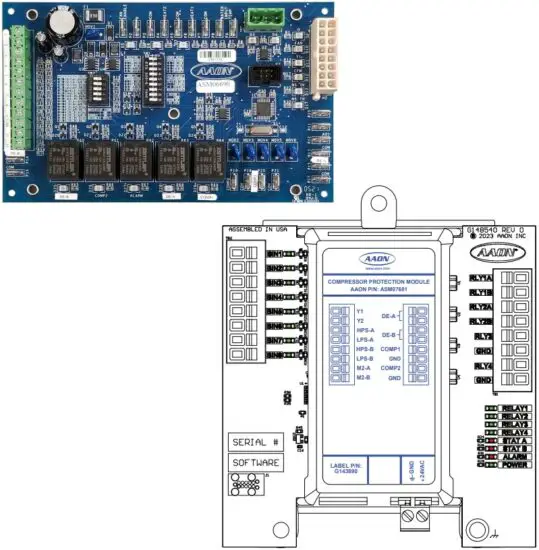
ASM06690, ASM07681 Compressor Protection Module
| PRODUCT NAME REVISION LOG | |
| REVISION AND DATE | CHANGE |
| Rev. A, December 15, 2021 | Original |
| Rev. B, February 9, 2022 | Added wiring for On/Off Compressors |
| Rev. C, December 18, 2023 | Added replacement part, wiring, and LED descriptions, updated layout |
| Rev. D, June 21, 2024 | Updated Dimensions |
| Rev. E, August 14, 2024 | Updated Illustrations |
| PRODUCT NAME PARTS REFERENCE | |
| PART DESCRIPTION | PART NUMBER |
| Compressor Protection Module | ASM06690 / ASM07681 |
All manuals are also available for download from www.aaon.com/controlsmanuals.
AAON
2425 South Yukon Ave.
Tulsa, OK 74107-2728
www.aaon.com
Factory Technical Support Phone: 918-382-6450
AAON Controls Support: 866-918-1100
It is the intent of AAON to provide accurate and current product information. However, in the interest of product improvement, AAON reserves the right to change pricing, specifications, and/or design of its product without notice, obligation, or liability.
AAON P/N:G100690, Rev. E
© August 2024 AAON Inc. All rights reserved.
AAON® is a registered trademark of AAON, Inc., Tulsa, OK.
Copeland® is a registered trademark of Emerson Electric Co., St.
Louis, MO. OMNIMATE® is a registered trademark of Weidmüller, Detmold, Klingenbergstraße, Germany
AAON assumes no responsibility for errors or omissions in this document.
This document is subject to change without notice.
OVERVIEW
General Information
Overview
The Compressor Protection Module is used in split systems as a stand-alone module. It provides additional protection for compressors in systems with self-resetting pressure switches. The module uses high pressure and low pressure switches to disable the compressor and enforce a minimum compressor off time when a fault occurs. It also limits the number of retries and locks out the compressor if it exceeds the maximum number of allowed faults. The Compressor Protection Module sequence is intended to help with the start up of units with microchannel coils and prevent nuisance lockouts when the coil is cold.
The Compressor Protection Module supports up to two compressors.
There is no staging or fail over functionality within the module; the compressors operate independently.
The ASM07681 is equipped with new OMNIMATE connectors for easier installation. See Figure 6, page 13.
Dimensions
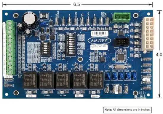 Figure 1: Compressor Protection Module Dimensions – ASM06690
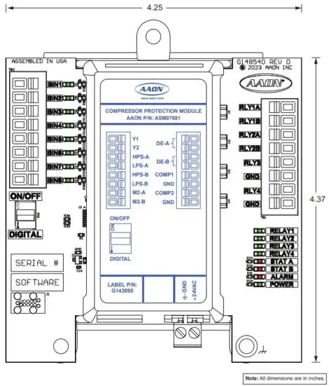 Figure 2: Compressor Protection Module Dimensions – ASM07681
INSTALLATION AND WIRING
Wiring
Wiring Overview
In general, most Compressor Protection Modules are installed and wired at the AAON factory. Some of the following information pertains to field wiring and may not apply to your installation if it was pre-wired at the factory. However, if troubleshooting of the module is required, it is a good idea to be familiar with the system wiring, no matter if it was factory or field wired.
Mounting
When the Compressor Protection Module is field mounted, it is important to mount it in a location that is free from extreme high or low temperatures, moisture, dust, and dirt. See Table 1, this page, for a list of the required operating conditions for the Compressor Protection Module.
The Compressor Protection Module is designed to be mounted via the four shoulder eyelets located on the corners of each circuit board.
CAUTION: Be careful not to damage the electronic components when mounting the module.
Electrical & Environmental Requirements
The Compressor Protection Module must be connected to a 24 VAC power source of the proper size for the calculated VA load requirements. All transformer sizing should be based on the VA rating listed in Table 1, this page.
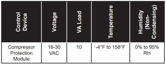 Table 1: Compressor Protection Module Specifications
Inputs and Outputs
I/O Map
See Table 2 and 3, this page, for Compressor Protection Module inputs and outputs.
| ASM06690 -Compressor Protection Module | |
| Inputs | |
| Pluggable Screw Terminal Block H4 | |
| 2 | Compressor A call from the main controller (Y1) |
| 3 | Compressor B call from the main controller (Y2) |
| 4 | High pressure switch for Compressor A (HPS-A) |
| 5 | Low pressure switch for Compressor A (LPS-A) |
| 6 | High pressure switch for Compressor B (HPS-B) |
| 7 | Low pressure switch for Compressor B (LPS-B) |
| 10 | Compressor A output from Copeland Controller (M2-A) |
| 11 | Compressor B output from Copeland Controller (M2-B) |
| 12 | Compressor control relay ground |
| Quick Disconnect Terminals | |
| P2-R | 24 VAC |
| P3-COM | Ground |
| Relays | |
| Quick Disconnect Terminals | |
| COMP1 | Compressor A 24 VAC output |
| COMP2 | Compressor B 24 VAC output |
| DE-A | Compressor A demand enable |
| DE-B | Compressor B demand enable |
| P21-COM | Compressor A ground |
| P19-COM | Compressor B ground |
Table 2: Inputs and Outputs – ASM06690
| Compressor Protection Module | |
| Inputs | |
| BIN1 | Compressor A call from the main controller (Y1) |
| BIN2 | Compressor B call from the main controller (Y2) |
| BIN3 | High pressure switch for Compressor A (HPS-A) |
| BIN4 | Low pressure switch for Compressor A (LPS-A) |
| BIN5 | High pressure switch for Compressor B (HPS-B) |
| BIN6 | Low pressure switch for Compressor B (LPS-B) |
| BIN7 | Compressor A output from Copeland Controller (M2-A) |
| BIN8 | Compressor B output from Copeland Controller (M2-B) |
| Relays | |
| RLY1A | DE-A (Compressor A demand enable) |
| RLY1B | RLY1 Common |
| RLY2A | DE-B (Compressor B demand enable) |
| RLY2B | RLY2 Common |
| RLY3 | COMP1 (Compressor A output) |
| GND | GROUND |
| RLY4 | COMP2 (Compressor B output) |
| GND | GROUND |
Table 3: Inputs and Outputs – ASM07681
Inputs and Outputs Descriptions
Compressor Protection Module I/Os
Compressor A call
This is the Compressor A call from the main controller.
Compressor B call
This is the Compressor B call from the main controller.
High pressure switch
This is the high pressure switch or compressor run status for Compressor A.
Low pressure switch
This is the low pressure switch for Compressor A.
High pressure switch
This is the high pressure switch or compressor run status for compressor B.
Low pressure switch
This is the low pressure switch for compressor B.
Compressor A output
This is the Compressor A output from the Copeland Controller.
Compressor B output
This is the Compressor B output from the Copeland Controller.
Compressor control relay ground (ASM06690 only)
This is the ground connection for the compressor control relay..
P2-R – 24 VAC input (ASM06690 only)
This is the 24 VAC input for the Compressor Protection Module.
Compressor A Output
This is the Compressor A 24 VAC output which energizes the compressor contactor.
Compressor A Enable
This is the Compressor A demand enable which energizes external relay to pass the demand VDC signal to Copeland Controller.
Compressor B Output
This is the Compressor B 24 VAC output which energizes the compressor contactor.
Compressor B Enable
This is the Compressor B demand enable which energizes the external relay to pass the demand VDC signal to the Copeland Controller.
ASM06690 – Single Compressor
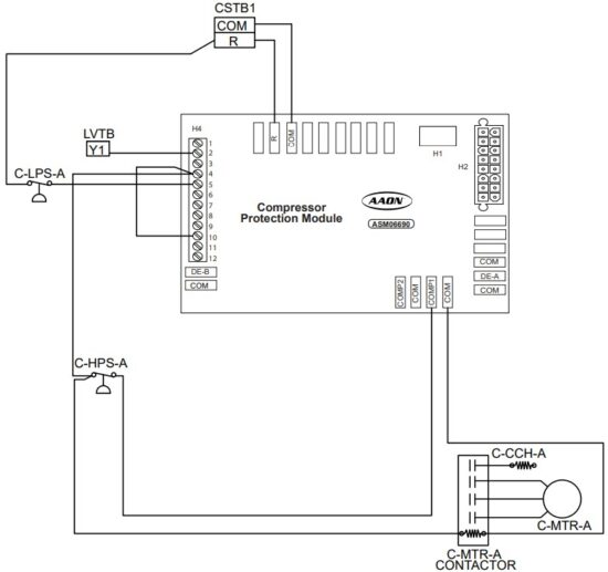 Figure 3: ASM06690 – Single Compressor
ASM06690 – Dual Compressor
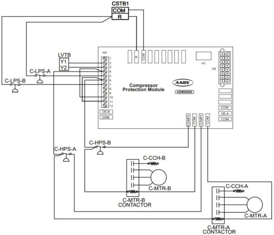 Figure 4: ASM06690 – Dual Compressor
ASM06690 – Single Digital Compressor
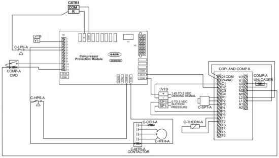 Figure 5: ASM06690 – Single Digital Compressor
ASM06690 – Digital and On/Off Compressor
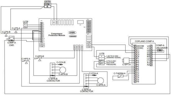 Figure 6: ASM06690 – Digital and On/Off Compressor
ASM06690 – Dual Digital Compressor
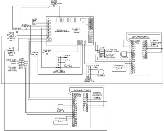 Figure 7: ASM06690 – Dual Digital Compressors
ASM07681 – Single Compressor
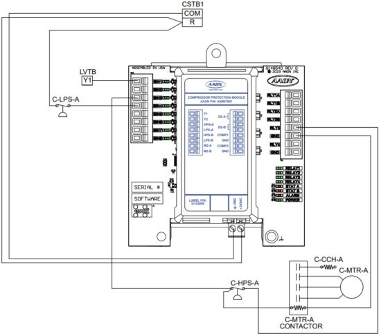 Figure 8: ASM07681 – Single Compressor
ASM07681 – Dual Compressor
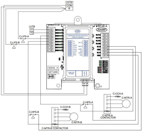 Figure 9: ASM07681 – Dual Compressor
ASM07681 – Single Digital Compressor
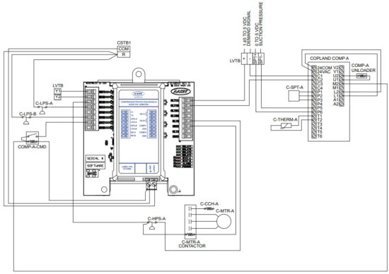 Figure 10: ASM07681 – Single Digital Compressor
ASM07681 – Digital and On/Off Compressor
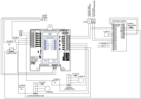 Figure 11: ASM07681 – Digital and On/Off Compressor
ASM07681 – Dual Digital Compressors
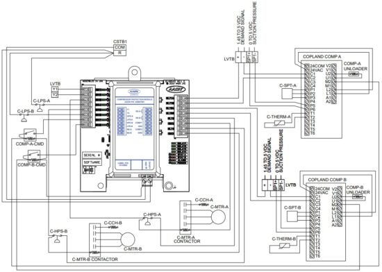 Figure 12: ASM07681 – Dual Digital Compressors
OMNIMATE® Connector – ASM07681 Only
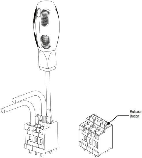 Figure 13: OMNIMATE Connector Instructions
SEQUENCE OF OPERATIONS
Operation Modes
Compressor Operation
The compressor operation is determined by the compressor call fromthe main controller and the compressor output from the Copeland Compressor Controller.
Sequence of Operation
Off
When the compressor call is not energized, the compressor relay output and demand enable will be de-energized.
Compressor Call Active
When the compressor call and the low pressure switch energize, the demand enable energizes, which allows the compressor demandsignal to pass from the main controller to the Copeland Controller.
NOTE: The compressor relay output will not energize if the low pressure switch is not energized. This could indicate a loss of charge in the system.
When the compressor output from the Copeland Controller is energized, the Compressor Protection Module will energize the compressor 24 VAC to energize the compressor output from the Copeland Controller. The low pressure switch and high pressure switch are ignored and will not trigger any alarms until the compressor output from the Copeland Controller is energized.
NOTE: This is to prevent false alarms on the Compressor Protection Module when the Copeland Controller is in its own minimum off time.
If the compressor output from the Copeland Controller is deenergized while the compressor call is still active, the Compressor Protection Module will de-energize the compressor 24 VAC, but keep the demand enable energized. The compressor 24 VAC will re-energize when the demand for the compressor rises above 10%. The off time in this case is enforced by the Copeland Controller.
When the compressor call de-energizes, the compressor 24 VAC and demand enable will de-energize and a minimum compressor off time of five minutes will be enforced. If the compressor call becomes re-energized, the compressor will not restart until the minimum off time has elapsed.
NOTE: There is no minimum on time enforced by the Compressor Protection Module.
High Pressure Alarm Sequence
If the high pressure switch is not energized within five seconds of the compressor output from the Copeland Controller being active or if the high pressure switch is de-energized while the compressor is running, a high pressure alarm will be triggered.
If an alarm occurs on startup or within the first 15 minutes of the compressor call, the module will allow four retries, and will lock out on the fifth fault.
If a fault occurs after the first 15 minutes of the compressor call, the module will allow one retry, and will lock out if another fault occurs within two hours.
The alarm will de-energize the compressor 24 VAC and demand enable for two minutes and then re-energize the demand enable.
The low pressure switch and high pressure switch will be ignored and not trigger an alarm until the compressor output from the Copeland Controller has re-energized. The compressor 24 VAC will energize once the compressor output from the Copeland Controller is energized.
The fault counter will reset to zero if the compressor call is removed or the compressor has run successfully for two hours since the last fault.
If the module is locked out, power to the module must be cycled to clear the lockout.
Operation Modes
Low Pressure Alarm Sequence
The Low Pressure Switch is ignored for one minute after the compressor contactor output becomes active.
NOTE: This alarm logic replaces a standalone timer-based low pressure switch bypass that defaults to five minutes. However, this five minutes is the default for the timer and has no relevance to the operation of the unit.
If the low pressure switch is de-energized for five seconds while the compressor is running, a low pressure alarm will be triggered and the compressor 24 VAC and demand enable will be de-energized.
If the compressor call is still active, the demand enable will be re-energized after five minutes. The low pressure switch and high pressure switch will be ignored and not trigger an alarm until the compressor output from the Copeland Controller has re-energized.
The compressor 24 VAC output will be energized once the compressor output from the Copeland Controller is energized.
The compressor will be locked out if three low pressure alarms occur within two hours.
If the compressor is locked out, power to the module must be cycled to clear the lockout.
TROUBLESHOOTING
Compressor Protection Module LED Diagnostics
Compressor Protection Module LEDs
See Figure 3, page 14, for LED locations. The LEDs and their uses are as follows:
Operation LED
POWER – This green LED will light up when 24 VAC power is applied to the module.
Output LEDs
COMP A RELAY – This green LED will light up when Compressor A Relay is active.
COMP B RELAY – This green LED will light up when Compressor B Relay is active.
Demand Enable A – This green LED will light up when the demand enable for Compressor A is active.
Demand Enable B – This green LED will light up when the demand enable for Compressor B is active.
Controller Alarms
LED Fault Codes
The Compressor Protection Module has two status LEDs (D3 and D4) on the board to indicate faults for Compressor A and B. A green status light indicates the unit is powered up and that the module is not detecting any fault conditions. A flashing red status light indicates the module has detected a fault condition and is now in alarm mode. The number of flashes indicates what alarm is present. See Table 3, this page, for blink code descriptions.
Lockout Alarms
The Compressor Protection Module has an Alarm LED on the board to indicate when an alarm is present. This LED will light up red if there is an active High Pressure Lockout or Low Suction Lockout alarm for either compressor.
| COMP A and B Alarm Status Blinks | Blink Code Description |
| 0 | No Alarms |
| 1 | High Pressure Alarms |
| 2 | High Pressure Lockout |
| 3 | Low Suction Alarm |
| 4 | Low Suction Lockout |
Table 4: Alarm Status LED Diagnostic Codes
Compressor Protection Module LED Locations – ASM06690
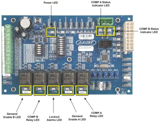 Figure 14: LED Locations and Descriptions – ASM06690
Compressor Protection Module LED Locations – ASM07681
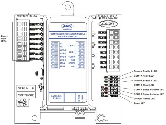 Figure 15: LED Locations and Descriptions – ASM07681
Compressor Protection Module Technical Guide
G100690 · Rev. E · 240814
AAON Controls Support: 866-918-1100
Monday through Friday, 7:00 AM to 5:00 PM
Central Standard Time
Controls Support website:
www.aaon.com/controlstechsupport
AAON Factory Technical Support: 918-382-6450
techsupport@aaon.com
NOTE: Before calling Technical Support, please have the model and serial number of the unit available.
PARTS: For replacement parts, please contact your local AAON Representative.
![]() 2425 South Yukon Ave • Tulsa, OK • 74107-2728
2425 South Yukon Ave • Tulsa, OK • 74107-2728
Ph: 918-583-2266 • Fax: 918-583-6094
AAON P/N: G100690, Rev. E
Printed in the USA • Copyright August 2024
• All Rights Reserved
Documents / Resources
 | AAON ASM06690, ASM07681 Compressor Protection Module [pdf] User Guide ASM06690, ASM07681, ASM06690 ASM07681 Compressor Protection Module, ASM06690 ASM07681, Compressor Protection Module, Protection Module, Module |